Motor vehicle lock with micro switch

A technology of turning the lock fork and moving it, which is applied in the direction of electric car locks, vehicle locks, building locks, etc., and can solve problems such as functional failures

Active Publication Date: 2019-03-08
KIEKERT AG
View PDF5 Cites 0 Cited by
  • Summary
  • Abstract
  • Description
  • Claims
  • Application Information

AI Technical Summary

Problems solved by technology

This may cause malfunction

Method used


Image

  • Motor vehicle lock with micro switch
  • Motor vehicle lock with micro switch

Examples


Embodiment Construction

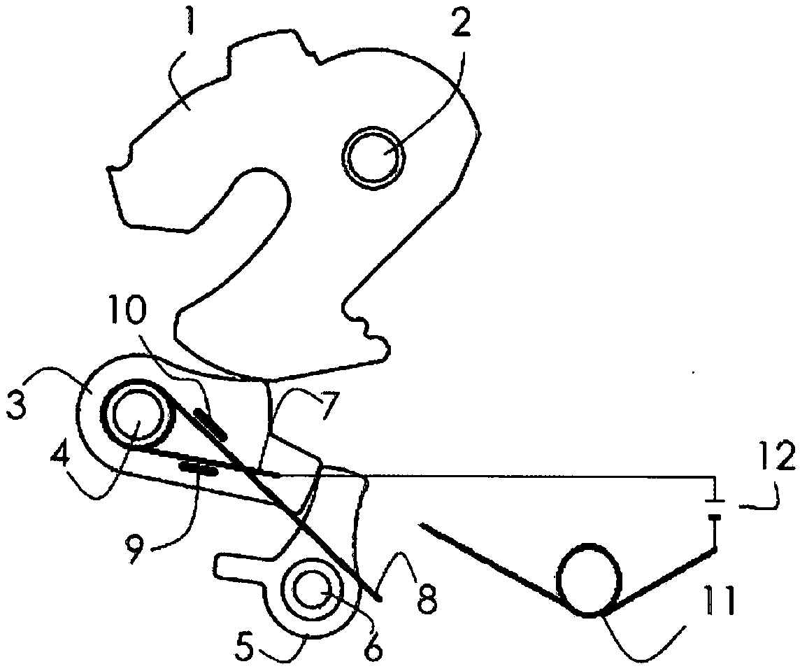
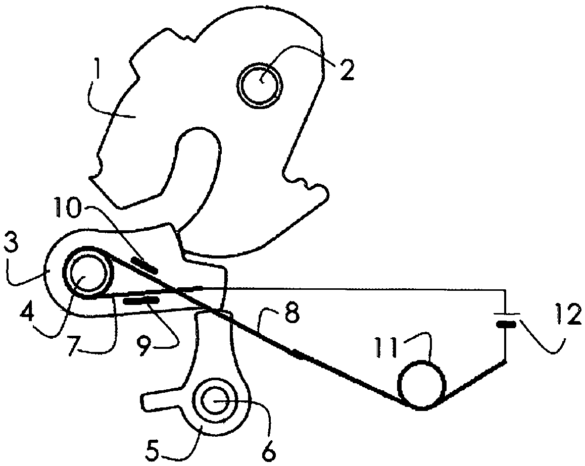
[0020] exist figure 1 with figure 2 shows a rotary latch 1 which can be rotated or swiveled about its axis 2 . The rotary locking fork 1 can be locked by means of the locking pawl 3 . The pawl 3 can pivot about its axis 4 . This locking device also includes a deadlock lever 5 which can pivot about its axis 6 .

[0021] The spring with the spring legs 7 and 8 is held in the region of or by the pawl shaft 4 and the webs 9 and 10 of the pawl 3 . The lugs 9 and 10 are arranged on the surface of the pawl 3 . The web can be angled or bent in section in order to surround and thus hold the spring legs 7 and 8 . Another spring 11 is also provided. The two spring legs 7 , 8 and the spring 11 are connected to a DC power source 12 .

[0022] figure 1 The locking device is shown in the unlocked state. The pawl 3 rests against a contour of the rotary catch 1, but does not lock the rotary catch. The blocking lever 5 bears against a contour of the pawl 3 without blocking the pawl 3...


PUM


Abstract

The invention relates to a lock with a locking device comprising a rotary catch and a pawl for blocking the rotary catch in the closed position of the lock. Identification means are also provided for identifying the position of the movable component of the lock. The identification means includes a spring mounted on the member. When the member and the spring connected to the member move, the spring opens or closes the electrical circuit. According to the invention, the position of the locking device can be determined reliably without fear of fatigue phenomena of the spring and consequent failures.

Description

technical field [0001] The invention relates to a lock for a motor vehicle, which has a locking device comprising a rotary locking fork and a pawl, with which the rotary locking fork can be locked in a locked position. The lock has identification means for identifying the position of the components of the locking device. Background technique [0002] As pointed out in document DE 10 2009 026 921 A1, the rotary yoke of a motor vehicle lock has a fork-shaped entry slit, also called an entry opening, when the door or vehicle cover is closed, also called The stop of the lock holder reaches this entry slit. The stop then rotates the rotary latch from the open position into the locked position. If the rotary locking fork reaches the locked position, the stop can no longer leave the entry slot of the rotary locking fork. In this locked position, the locking pawl blocks the rotary locking fork, so that the rotary locking fork can no longer be pivoted back into the open position. ...

Claims


Application Information

Patent Timeline
Patent Type & Authority Patents(China)
IPC IPC(8): E05B85/26E05B81/64
CPCE05B81/64E05B85/26E05B2015/0444E05B15/04E05B81/20E05B81/66
Inventor A·汉德克M·库贝克
Owner KIEKERT AG
Why Eureka
Try Eureka