cooling system

A cooling system and cooling device technology, applied in refrigerators, refrigeration components, refrigeration and liquefaction, etc., can solve the problems of inability to adjust the temperature of circulating liquid, no circulating liquid, and inability to fully perform

Inactive Publication Date: 2019-09-17
YANMAR POWER TECHNOLOGY CO LTD
View PDF2 Cites 0 Cited by
  • Summary
  • Abstract
  • Description
  • Claims
  • Application Information

AI Technical Summary

Problems solved by technology

[0003] On the other hand, for a heat pump cooling device that regulates the temperature of a temperature-regulating (for example, air-conditioning) circulating fluid as a heat medium by the condensation heat or evaporation heat of the refrigerant, there is also a defrosting operation (i.e., In the case of removing frost adhering to the piping in the refrigerant-air heat exchanger), in the case of defrosting operation in a cooling system connected to multiple heat pump cooling devices, during the defrosting operation The temperature of the circulating fluid is not adjusted, so if more than a specified number of cooling devices (especially all cooling devices) perform defrosting operation at the same time, the temperature of the circulating fluid cannot be adjusted sufficiently (or not at all)

Method used


Image

  • cooling system
  • cooling system
  • cooling system

Examples


Embodiment Construction

[0026] Hereinafter, embodiments of the present invention will be described with reference to the drawings.

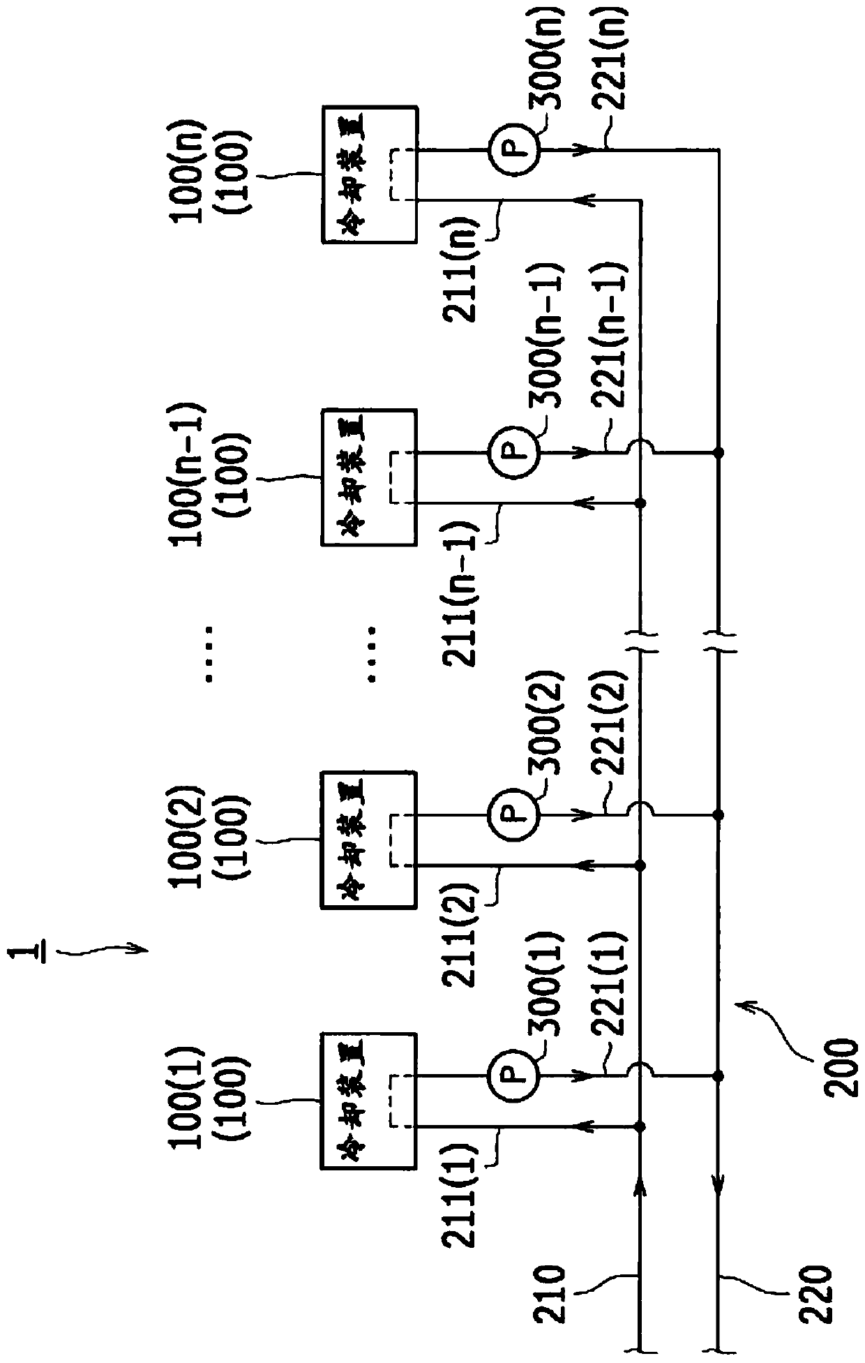
[0027] figure 1 It is a system diagram showing the schematic configuration of the cooling system 1 according to the embodiment of the present invention.

[0028] figure 1 The illustrated cooling system 1 is configured by connecting a plurality of heat pump type cooling devices 100 in parallel. In addition, hereafter, a heat pump type cooling device may be referred to simply as a cooling device.

[0029] Specifically, the cooling system 1 includes a plurality of cooling devices 100 ( 1 ) to 100 (n) (n is an integer equal to or greater than 2) and a circulating liquid circuit 200 . Each of the cooling devices 100 ( 1 ) to 100 ( n ) has the same configuration. Therefore, the rated outputs of the respective cooling devices 100 ( 1 ) to 100 ( n ) are all set to be the same. In addition, in the following description, only the code|symbol 100 is attached|subjected to each...


PUM


Abstract

In the cooling system, any one of the plurality of cooling devices is designated as the cooling device of the main machine. A cooling device that requires a defrosting operation among the plurality of cooling devices requests a defrosting operation to the cooling device of the master unit. The cooling device of the master unit permits the defrosting operation for a predetermined number of cooling devices that request the defrosting operation first in order. The cooling device on standby for the defrosting operation requests a defrosting operation to the cooling device of the main unit at a predetermined cycle. When there are multiple cooling devices on standby for the defrosting operation, the cooling device of the main unit permits the next defrosting operation in descending order of the number of requests for the defrosting operation or the request time.

Description

technical field [0001] The present invention relates to a cooling system in which a plurality of heat pump chillers are connected, wherein the chillers adjust the temperature of a temperature-regulating circulating fluid as a heat medium by the heat of condensation or evaporation of refrigerant. Background technique [0002] Conventionally, a structure is known in which, in a heat pump, when a refrigerant-air heat exchanger for exchanging heat between refrigerant and air functions as an evaporator, a defrost operation is performed to remove the heat caused by external factors. Frost that adheres to piping in the refrigerant-air heat exchanger due to conditions such as gas temperature (for example, refer to Patent Document 1). Specifically, Patent Document 1 discloses a configuration in which the expansion valve for the indoor heat exchanger is fully closed during the defrosting operation, the refrigerant is not allowed to flow into the indoor heat exchanger, and heat is abso...

Claims


Application Information

Patent Timeline
Patent Type & Authority Patents(China)
IPC IPC(8): F25B47/02F24F11/89F25B1/00
CPCF25B13/00F25B27/00F25B47/025F25B49/02F25B2313/003F25B2313/02322F25B2327/001F25B2400/06F24F11/63F24F11/41F24F11/89
Inventor 南本宏太郎田中雄一郎西裕之
Owner YANMAR POWER TECHNOLOGY CO LTD
Why Eureka
Try Eureka