
Terminal and method for detecting ambient brightness

A technology of ambient light and ambient light sensor, which is applied in the field of wireless communication, can solve the problems of inaccurate detection results of ambient light sensor and inability to accurately detect the brightness of ambient light, etc., and achieve the effect of improving comfort

Active Publication Date: 2017-02-22
HUAWEI TECH CO LTD
View PDF6 Cites 78 Cited by
  • Summary
  • Abstract
  • Description
  • Claims
  • Application Information

AI Technical Summary

Problems solved by technology

[0003] When the ambient light sensor is placed inside the terminal and under the display screen to detect changes in ambient light through transmitted light, the detection result will be affected by the internal light of the terminal display screen, such as the backlight, or the reflected light of the screen itself on the screen surface , leading to inaccurate detection results of the ambient light sensor. For example, when the terminal moves from a bright place to a dark place, the ambient light sensor cannot accurately detect the brightness of the ambient light due to the influence of the internal light on the display screen of the terminal.

Method used


Image

  • Terminal and method for detecting ambient brightness
  • Terminal and method for detecting ambient brightness
  • Terminal and method for detecting ambient brightness

Examples


no. 1 example

[0069] Taking organic light-emitting diode (OLED) screens as an example, figure 2 It is a schematic structural diagram of a wearable device provided by an embodiment of the present invention. Such as figure 2 As shown, the screen 120 has an upper surface 1201 and a lower surface 1202 , the black glue layer 1203 is located on the lower surface 1202 of the screen, and the ambient light sensor 130 is disposed in the hollow area 1204 of the black glue layer 1203 . The ambient light sensor 130 can be placed on the FPC soft board 140 . The photosensitive element 1301 of the ambient light sensor faces the screen 120 and is located on the lower surface 1202 of the screen 120 . The ambient light sensor 130 and the screen 120 can be connected to the processor 110 through FPC respectively.

[0070] It can be understood that the black glue layer 1203 in this embodiment can have different names according to its different functions, for example, a light-shielding black glue layer with a l...

no. 2 example

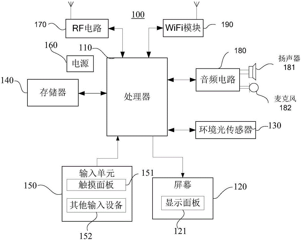
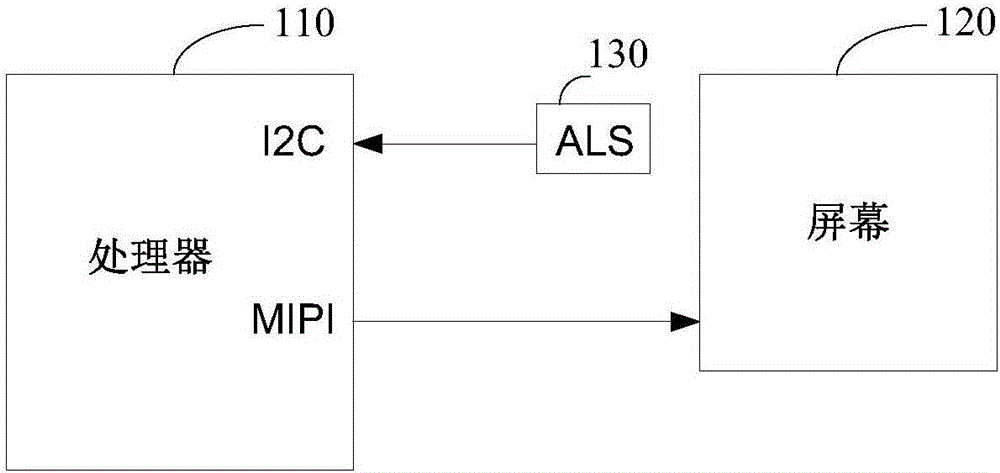
[0113] can refer to figure 2 and 3 , the second embodiment of the present invention also provides a wearable device. Wherein, the wearable device includes a processor 110 , an ambient light sensor 130 and a screen 120 . The ambient light sensor 130 and the screen 120 are respectively connected to the processor 110 . The photosensitive element of the ambient light sensor 130 faces the screen and is located on the lower surface of the screen. After the screen 120 is lit, within the duration of human vision, the processor 110 controls the image data, and the grayscale value of the controlled image data is less than or equal to the first threshold; Inside, the ambient light sensor 130 detects the brightness of the first ambient light where the wearable device is located.

[0114] Specifically, the wearable device may include an FPC soft board 140 , the ambient light sensor 130 may be placed on the FPC soft board 140 , and the ambient light sensor 130 may be connected to the p...


PUM


Abstract

The invention provides a terminal (100) and a method for detecting ambient brightness. The terminal (100) comprises a processor (110), an ambient light sensor (130) and a screen (120). The ambient light sensor (130) and the screen (120) are connected with the processor (110). A light sensing element (1301) of the ambient light sensor (130) faces the screen (120) and is arranged at the lower surface of the screen (120). After the screen (120) is lightened, in the retentivity time of human eyes, the processor (110) adjusts the first brightness of the screen (120) to below a first threshold (601); and in the retentivity time of the human eyes, the ambient light sensor (130) detects the brightness (602) of first ambient light in which the terminal (100) exists. The terminal (100) can eliminate non-ambient light which enters the ambient light sensor (130) so that the ambient light sensor (130) can detect the relatively true brightness of the ambient light.

Description

technical field [0001] Embodiments of the present invention relate to the field of wireless communication, and in particular, to a terminal and a method for detecting ambient light brightness. Background technique [0002] In order to enable the human eye to better observe the screen content when the light changes, terminals such as mobile phones and wearable devices will include ambient light sensors (ALS, ambient light sensor) to detect the brightness of the external ambient light where the terminal is located. When the ambient light sensor detects that the brightness of the ambient light changes, the terminal adjusts the brightness of the screen according to the detection result of the ambient light sensor, so that human eyes can better observe the screen. [0003] When the ambient light sensor is placed inside the terminal and under the display screen to detect changes in ambient light through transmitted light, the detection result will be affected by the internal light...

Claims


Application Information

Patent Timeline
IPC IPC(8): G06F3/0487G09G5/10
CPCG06F3/0487G09G5/10G01J1/00G09G2320/0626G09G2360/144G09G3/20H10K59/13H10K50/00G01J1/4204G01J1/44G06F3/041G09G3/2007G09G3/3208G09G2320/064G09G2354/00
Inventor 王希林
Owner HUAWEI TECH CO LTD
Learn More