Unlock instant, AI-driven research and patent intelligence for your innovation.

Apparatus and method for displaying location information

An imaging device and technology for marking information, applied in the field of location information, can solve problems such as operator embarrassment

Inactive Publication Date: 2019-08-16
SIEMENS HEALTHCARE GMBH
View PDF7 Cites 0 Cited by
  • Summary
  • Abstract
  • Description
  • Claims
  • Application Information

AI Technical Summary

Problems solved by technology

Seeing the position of the selected slice relative to the visually indicated inspection plane can be awkward for the operator

Method used


Image

  • Apparatus and method for displaying location information
  • Apparatus and method for displaying location information
  • Apparatus and method for displaying location information

Examples


Embodiment Construction

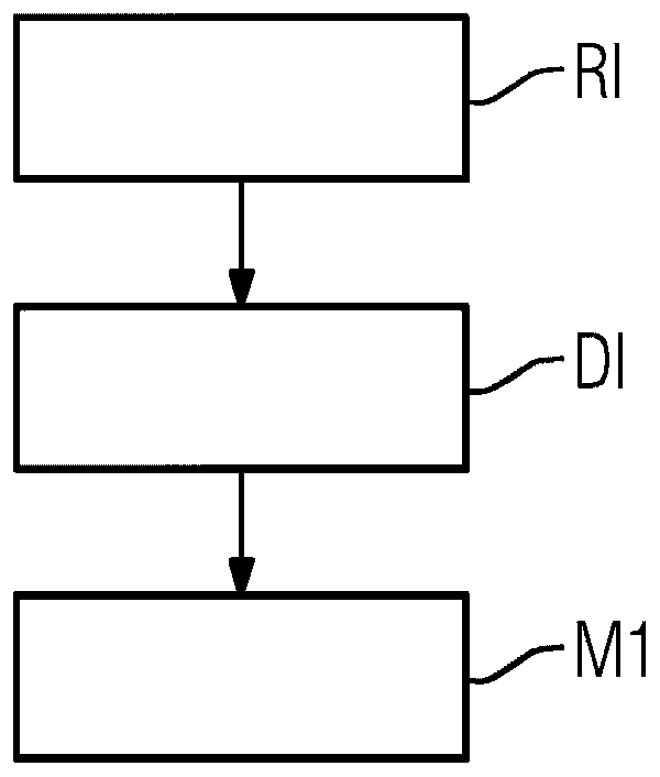
[0063] figure 1 shows a flow chart of a method according to a first embodiment of the invention for displaying position information relating to the position of the region of interest 14 of the patient 13 relative to the examination units 26, 28 of the imaging device 1, Therein, the first inspection plane E1 can be allocated (in particular, assigned) to the inspection units 26, 28, wherein the camera 61 is arranged relative to the inspection units 26, 28 such that the lens through the camera 61 is located in the same direction as the first inspection unit. The three non-collinear reference points R1A, R1B, R1C in the first reference plane R1 parallel to the plane E1 are mapped to the three collinear first image points I1A, I1B, I1C located on the first row, in step In RI, a camera image CI of the region of interest 14 is captured by the camera 61 . In step DI, a positioning image is displayed, wherein the positioning image PI has a camera image CI. In step M1, first marker in...


PUM


Abstract

The invention relates to a method for displaying positional information relating to the position of a region of interest of a patient relative to an examination unit of an imaging device, wherein a first examination plane can be assigned to the examination unit, wherein a camera is relative to the examination unit set so that through the lens of the camera, three non-collinear reference points located in a first reference plane parallel to the first inspection plane are mapped to three collinear first image points located on the first row, wherein , the method comprising the steps of: -capturing a camera image of the region of interest by a camera, -displaying a positioning image, wherein the positioning image has a camera image, -displaying first marker information related to the position of the first line in the positioning image .

Description

technical field [0001] The invention relates to a method for displaying position information about the position of a region of interest of a patient relative to an examination unit of an imaging device. The invention also relates to a method for positioning a patient relative to an examination unit, and an imaging device. Background technique [0002] In order to examine a patient by means of an imaging device, the position of a region of interest of the patient relative to an examination unit of the imaging device is usually determined and / or adjusted. For this purpose, the patient can eg be positioned relative to the examination unit such that the selected slice of the region of interest lies in an examination plane which can be assigned (in particular assigned) to the examination unit. On the basis of this position of the region of interest, for example a topogram and / or a conventional radiographic image for planning the acquisition of the imaging data set may be obtaine...

Claims


Application Information

Patent Timeline
Patent Type & Authority Patents(China)
IPC IPC(8): A61B6/03A61B6/04G01R33/28G01R33/54
CPCA61B5/748A61B6/469G06T7/0012G06T11/005G06T2207/10072A61B6/032G01R33/283G01R33/543A61B6/0492A61B5/055A61B5/00
Inventor T·汉内曼B·拉科
Owner SIEMENS HEALTHCARE GMBH