A control method and device for preventing magnetic saturation of coupling reactor

A coupling reactance and control method technology, applied in the field of power electronics, can solve problems such as complex compensation methods and complex power frequency components, and achieve the effect of simplifying the compensation process and preventing magnetic saturation

Active Publication Date: 2018-10-02
EMERSON NETWORK POWER CO LTD
View PDF4 Cites 0 Cited by
  • Summary
  • Abstract
  • Description
  • Claims
  • Application Information

AI Technical Summary

Problems solved by technology

For the power frequency component in the circulating current, when the power frequency component in the circulating current is detected and compensated by the fast Fourier transform method, it is necessary to continuously pass the fast Fourier transform method during the entire operation of the inverter circuit. To detect the power frequency component in the circulating current, and because the fast Fourier transform method is used to detect the power frequency component in the circulating current is more complicated, this will complicate the compensation method of the power frequency component in the circulating current
[0006] To sum up, when compensating the power frequency component in the circulating current at present, it is necessary to continuously detect the power frequency component in the circulating current through the method of fast Fourier transform, and the method of fast Fourier transform is used to detect The power frequency component in the circulating current is more complicated, so this will complicate the compensation method of the power frequency component in the circulating current

Method used


Image

  • A control method and device for preventing magnetic saturation of coupling reactor
  • A control method and device for preventing magnetic saturation of coupling reactor
  • A control method and device for preventing magnetic saturation of coupling reactor

Examples


Embodiment Construction

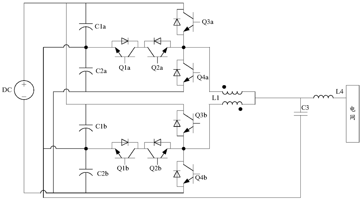
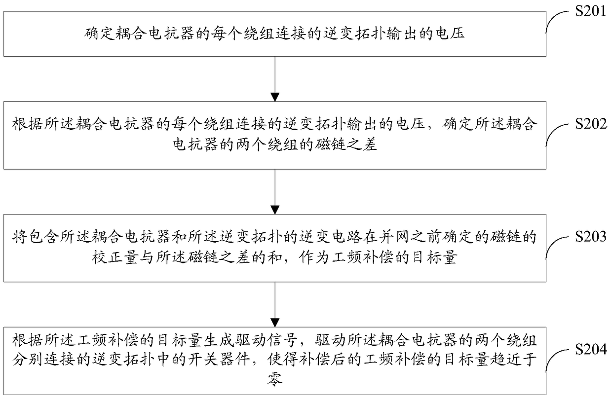
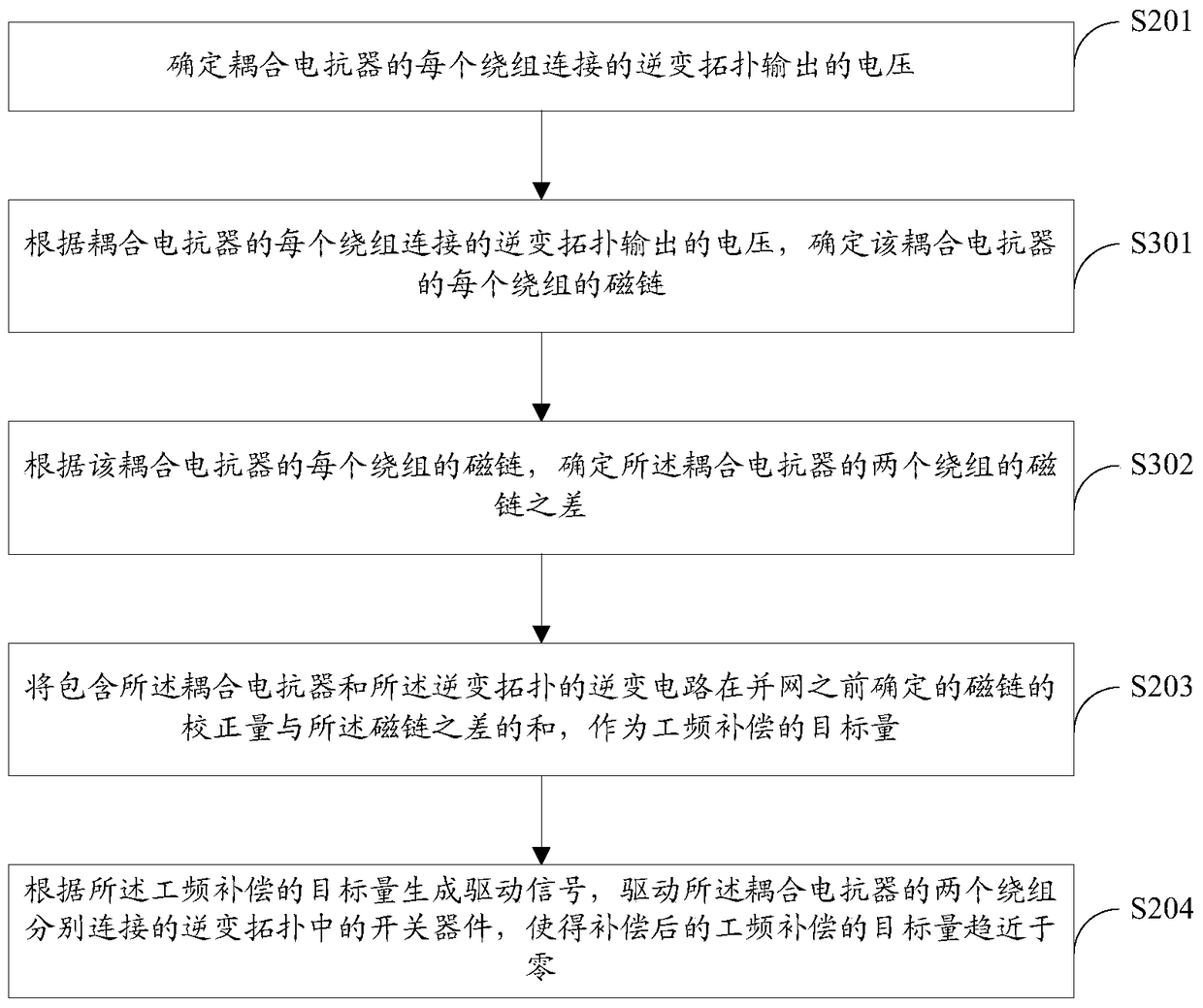
[0029] The control method and device for preventing the magnetic saturation of the coupling reactor provided by the embodiments of the present invention are determined by determining the difference between the magnetic flux linkages of the two windings of the coupling reactor and the inverter circuit including the coupling reactor and the inverter topology before grid connection The sum of the correction amount of the flux linkage compensates the power frequency component of the circulating current in the inverter circuit, thereby avoiding the use of fast Fourier transform in the compensation process and simplifying the compensation process.

[0030] For the coupling reactor connecting two inverter topologies, the flux linkage value of the magnetic column part of the coupling reactor depends on the branch current (that is, the current output by each inverter topology) and the size of the circulating current. The flux linkage value of the yoke part is mainly affected by the circula...


PUM


Abstract

The embodiment of the present invention provides a control method and apparatus to prevent coupling reactor's magnetic saturation, and a compensation method for simplifying the power frequency component in the conventional circulation. The method comprises: determining the voltage outputted by the inversion topology in connection with each winding of the coupling reactor; according to the voltage outputted by the inversion topology in connection with each winding of the coupling reactor, determining the difference in the flux linkage of the two windings of the coupling reactor; using the sum of the correction amount of the flux linkage determined by the inversion circuit before being connected to a power grid and the difference in the flux linkage as the target amount of power frequency compensation wherein the inversion circuit includes the coupling reactor and the inversion topology; and generating a driving signal in accordance with the target amount of the power frequency compensation to drive the two windings of the coupling reactor to be connected respectively with the switch devices in the inversion topology so that the target amount of power frequency compensation approaches zero.

Description

Technical field [0001] The present invention relates to the field of power electronics technology, and in particular to a control method and device for preventing magnetic saturation of a coupling reactor. Background technique [0002] figure 1 A five-level inverter circuit composed of T-type three-level inverter topology and coupled reactor L1. This five-level inverter circuit includes inverter topology A and inverter topology B. Inverter topology A includes switches Device Q1a, switching device Q2a, switching device Q3a, and switching device Q4a; inverter topology B includes switching device Q1b, switching device Q2b, switching device Q3b, and switching device Q4b; the output current of inverter topology A and inverter topology B After the output current is filtered by the coupling reactor L1, it is filtered again by the filter circuit formed by the capacitor C3 and the reactor L4 and then merged into the power grid. figure 1 The shown inverter circuit also includes a bus capac...

Claims


Application Information

Patent Timeline
Patent Type & Authority Patents(China)
IPC IPC(8): H02M7/48
Inventor 崔志洋王晛马志军靳广超
Owner EMERSON NETWORK POWER CO LTD
Why Eureka
Try Eureka