A horizontal compressor and temperature adjustment equipment

A compressor and horizontal technology, which is used in the field of horizontal compressors and temperature adjustment equipment, can solve the problems of inability to seal, the sliding vane and the cylinder are not tightly sealed, and the pressure is reduced.

Active Publication Date: 2018-09-07
GREE ELECTRIC APPLIANCES INC +1
View PDF8 Cites 2 Cited by
  • Summary
  • Abstract
  • Description
  • Claims
  • Application Information

AI Technical Summary

Problems solved by technology

[0004] The necessary condition for the formation and sealing of the compression chamber is that the sliding vane in the rotor is against the cylinder wall, and at the moment the compressor is started, the sliding vane is thrown out of the sliding vane slot quickly, and a cavity will be formed in the sliding vane slot. The pressure at the place drops rapidly, and it is very easy to retract into the slide groove when it contacts the cylinder, resulting in a poor or even impossible seal between the slide and the cylinder.

Method used


Image

  • A horizontal compressor and temperature adjustment equipment
  • A horizontal compressor and temperature adjustment equipment
  • A horizontal compressor and temperature adjustment equipment

Examples


Embodiment Construction

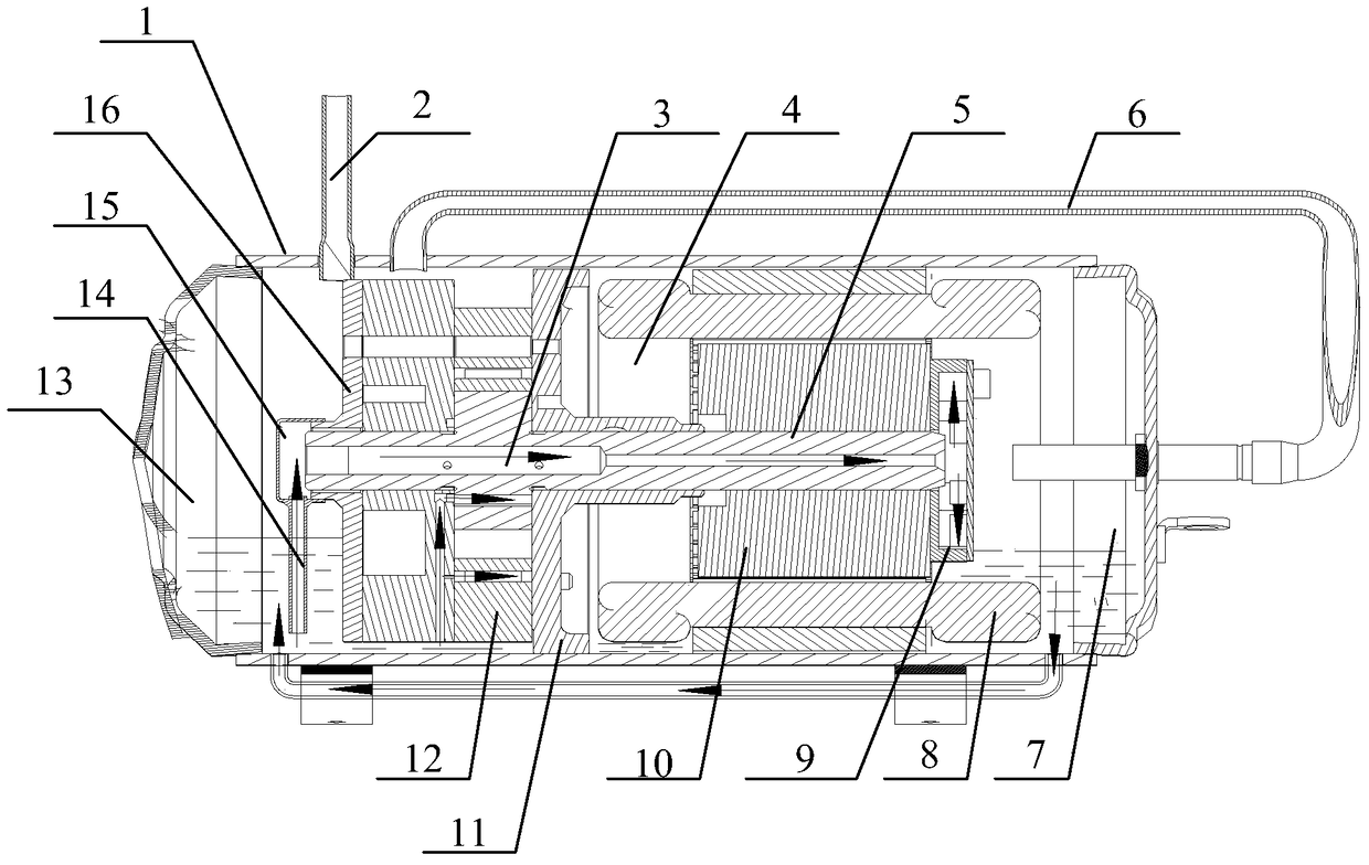
[0035] One of the cores of the present invention is to provide a horizontal compressor to ensure that the sliding vane can be extended smoothly when the compressor is started, and the sliding vane and the cylinder can maintain a proper adhesion force during normal operation, thereby improving compression The reliability of the machine.

[0036] Another core of the present invention is to provide a temperature regulating device with the above-mentioned horizontal compressor.

[0037] In order to enable those skilled in the art to better understand the solution of the present invention, the present invention will be further described in detail below with reference to the accompanying drawings and specific embodiments.

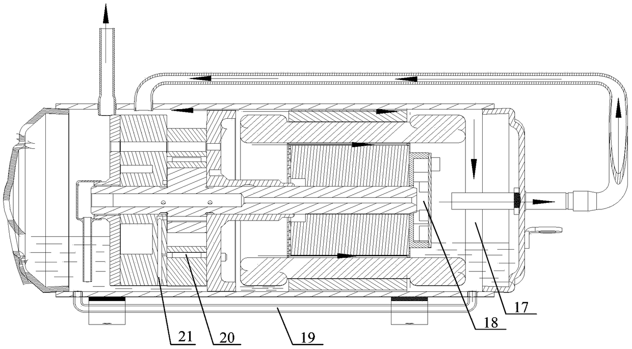
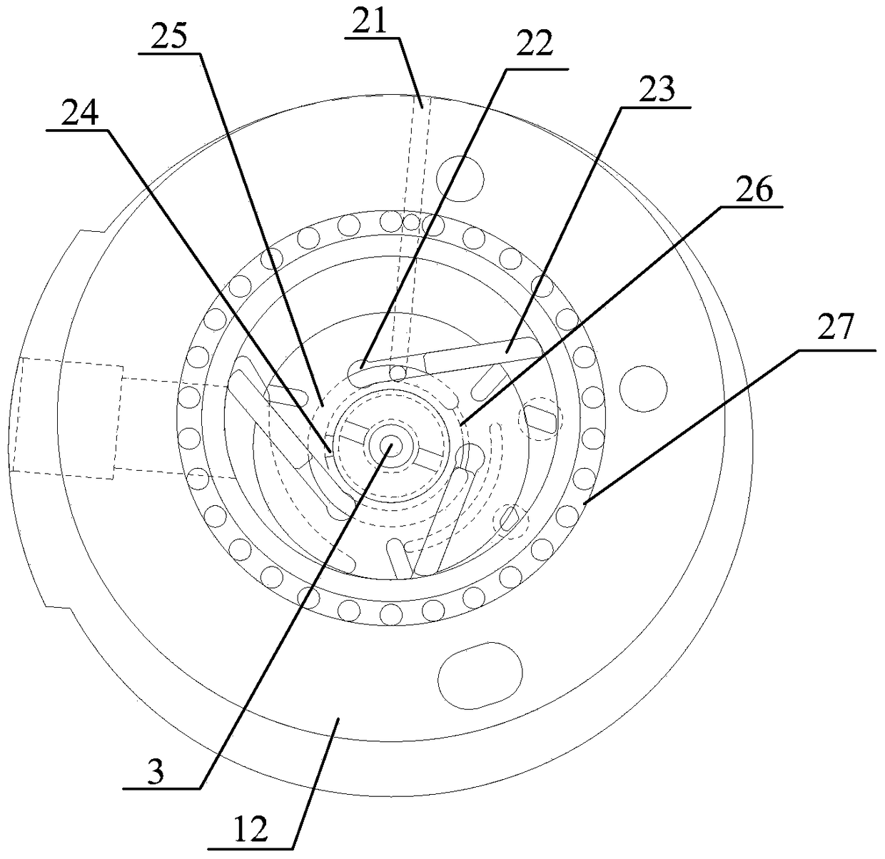
[0038] Please refer to Figure 1 to Figure 4 , figure 1 Is a schematic cross-sectional view of a horizontal compressor showing the flow direction of lubricating oil in an embodiment of the present invention, figure 2 Is a schematic cross-sectional view of a horizontal...


PUM


Abstract

The invention relates to a horizontal compressor which comprises a shell, a lower flange, an air cylinder, an upper flange and a motor. The lower flange, the air cylinder, the upper flange and the motor are sequentially arranged in the shell. An oil storage cavity is formed by the lower flange and the shell. A rotor is rotationally arranged in the air cylinder through a main shaft. The horizontal compressor further comprises a center oil hole penetrating the main shaft, a radial hole formed in the main shaft and communicating with the center oil hole, an oiling pipe fixedly connected to the end, located in the oil storage cavity, of the main shaft and communicating with the center oil hole, a lower flange back pressure groove formed in the lower flange and communicating with a sliding piece installation groove of the rotor, a groove for communicating the lower flange back pressure groove and the radial hole of the main shaft, an exhaust cavity communicating with an exhaust hole of the air cylinder and the center oil hole of the main shaft, and a fan installed at the other end of the fan, wherein the bottom end of the oiling pipe is close to the bottom of the oil storage cavity. According to the horizontal compressor, smooth stretching-out of a sliding piece during starting of the compressor and attachment between the sliding piece and the air cylinder during normal running of the compressor are effectively ensured. The invention further discloses a temperature adjusting device comprising the horizontal compressor.

Description

Technical field [0001] The present invention relates to the technical field of compressor manufacturing, in particular to a horizontal compressor and temperature regulation equipment. Background technique [0002] When the horizontal compressor is installed, the compressor is horizontal or close to the horizontal position, which greatly reduces the installation height of the horizontal compressor, which can effectively save installation space. Therefore, the horizontal compressor is used in the freezing or refrigeration display cabinet, and the vehicle freezing It has been widely used in equipment and vehicle air conditioning. [0003] The sliding vane type horizontal compressor usually includes a cylinder, a rotor that works in conjunction with the cylinder, and a sliding vane set in the rotor. During the operation, the sliding vane will be thrown out of the sliding vane groove under the action of the centrifugal force of the rotor and interact with The cylinders offset, thereby ...

Claims


Application Information

Patent Timeline
Patent Type & Authority Patents(China)
IPC IPC(8): F04C18/344F04C29/04F04C29/02
Inventor 杨国蟒徐嘉任丽萍万鹏凯罗发游吴飞
Owner GREE ELECTRIC APPLIANCES INC
Why Eureka
Try Eureka