
Optical detection device

An optical detection and sub-eye technology, which is applied in the field of optical reconnaissance and detection, can solve the problems of low reliability of detection devices and missing important targets, and achieve the effects of improving accuracy, ensuring angular resolution, and ensuring pixel values

Active Publication Date: 2017-03-08
北京航天晨信科技有限责任公司
View PDF15 Cites 2 Cited by
  • Summary
  • Abstract
  • Description
  • Claims
  • Application Information

AI Technical Summary

Problems solved by technology

[0007] The existing technical solution of using mechanical scanning to achieve staring imaging, although it can meet the requirements of large field of view and angular resolution, but in the application, there will be situations where important targets are missed due to the relative movement between the reconnaissance detection device and the target , the reliability of the detection device is low

Method used


Image

  • Optical detection device
  • Optical detection device
  • Optical detection device

Examples


Embodiment 1

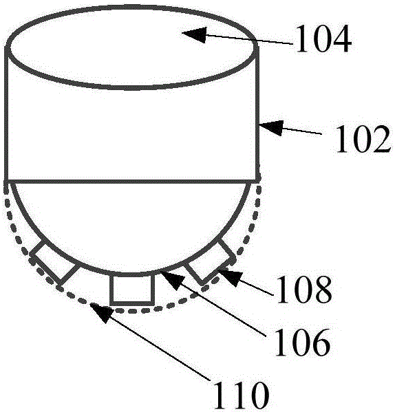
[0028] Reference figure 1 , Shows a schematic diagram of the external structure of an optical detection device according to the first embodiment of the present invention.

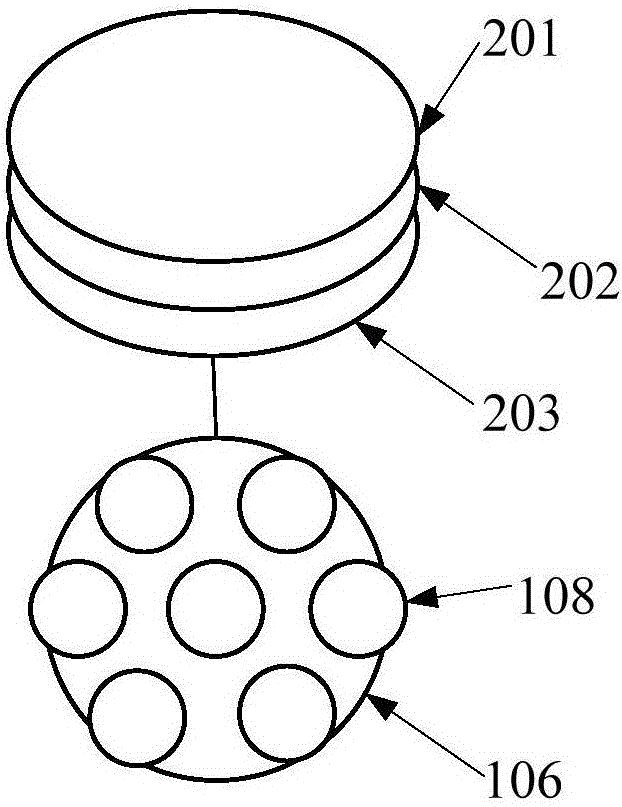
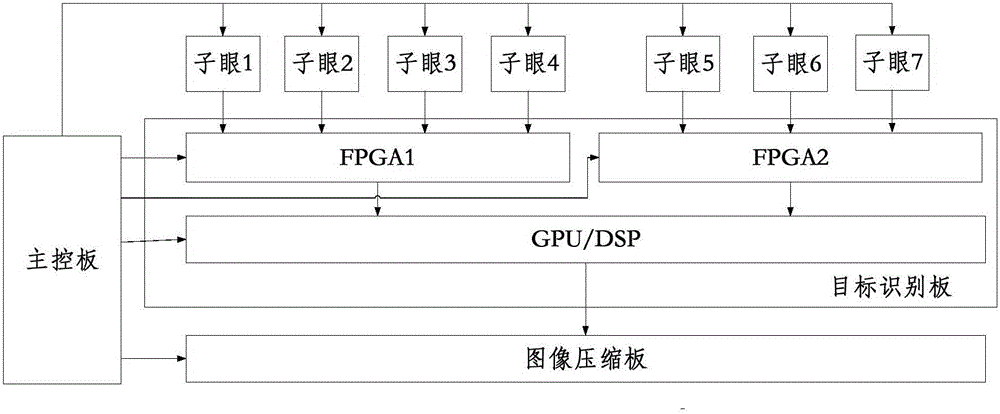
[0029] The optical detection device in the present invention includes: a coverless casing, a main control board, an image compression board, a target recognition board, a symmetric arcuate sub-eye support structure, and a plurality of sub-eyes. The main control board, image compression board and target recognition board are installed inside the shell, the supporting structure is fixed on the uncovered side of the shell, and the arc apex of the supporting structure is far away from the shell; the sub-eyes are distributed and installed outside the supporting structure On each ring line on the surface, each sub-eye includes an optical lens and an optical detector; the main control board is connected to the optical detector, target recognition board and image compression board of each sub-eye, and each sub-eye is c...

Embodiment 2

[0049] Reference Figure 4 , Shows a schematic diagram of the external structure of an optical detection device according to the second embodiment of the present invention.

[0050] In the embodiment of the present invention, an optical detection device including nineteen sub-eyes and two target recognition plates is taken as an example to describe the optical detection device of the embodiment of the present invention.

[0051] Such as Figure 4 As shown, the optical detection device of the embodiment of the present invention includes: a coverless housing (combined by a cylindrical aluminum alloy housing 302 and a circular bottom housing 304), a symmetric arcuate eye support structure 306 (this specific embodiment The supporting structure is a hemispherical shape), the sub-eyes 308 distributed on the outer surface of the supporting structure, and the hemispherical light-transmitting cover 310 matching the arc shape of the sub-eye supporting structure 306. The supporting structure ...


PUM


Abstract

The embodiment of the invention provides an optical detection device. The device comprises an uncovered shell, a main control board, an image compression board, a target identification board, a symmetrical arc sub-eye support structure, and multiple sub-eyes. The main control board, the image compression board and the target identification board are installed inside the shell. The support structure is fixed on the uncovered side of the shell, and the arc vertexes of the support structure are away from the shell. The sub-eyes are distributed and installed on loop lines on the outer surface of the support structure, and each sub-eye includes an optical lens and an optical detector. The main control board is connected with the optical detectors of the sub-eyes, the target identification board and the image compression board, the sub-eyes are connected with the target identification board, and the target identification board is connected with the image compression board. Through the optical detection device provided by the embodiment of the invention, precise and real-time detection for a large target is realized.

Description

Technical field [0001] The present invention relates to the technical field of optical reconnaissance and detection, in particular to an optical detection device. Background technique [0002] In many application fields such as military and civilian, there is a strong demand for large field of view and high-resolution optical detection systems. However, traditional visible light reconnaissance and detection devices are restricted by the technical level and physical principles, and high angular resolution and large field of view cannot be taken into account. Therefore, it is impossible to reliably meet the requirements of airborne or boatborne large-scale target detection and recognition. [0003] At present, the following two methods are mainly used to achieve airborne or boatborne large-scale target reconnaissance detection: [0004] The first type: the use of specially designed large field of view optical lens to achieve large-scale detection. [0005] Although the existing detecti...

Claims


Application Information

Patent Timeline
Patent Type & Authority Applications(China)
IPC IPC(8): G01V8/10
Inventor 曹扬胡荣吴京辉邵光征周武张佩
Owner 北京航天晨信科技有限责任公司
Learn More