
Angle-adjustable monitoring device and method based on millimeter-wave radar

A millimeter-wave radar and monitoring device technology, applied in the radar field, can solve the problems of not having the height of the target from the ground, accidents, and the millimeter-wave radar cannot recognize the height of the target from the ground, etc., to achieve low cost, guaranteed effect, and reduced effect of possibility

Active Publication Date: 2022-07-29
深圳市国天电子股份有限公司
View PDF13 Cites 0 Cited by
  • Summary
  • Abstract
  • Description
  • Claims
  • Application Information

AI Technical Summary

Problems solved by technology

[0003] However, due to cost constraints, the current vehicle-mounted millimeter-wave radar only sets the angular resolution of the plane, that is, through multiple antennas with transmission and reception, it has a certain angular resolution, and then realizes the identification and distinction of vehicles in different lanes. This is also because of this. There is no distinction made in the vertical direction, so the millimeter-wave radar cannot recognize the height of the target from the ground, so there is a risk of accidents. It has happened before that when a certain brand of vehicles was driving at high speed through automatic driving, the front The white container truck was identified as Baiyun, and then collided with the vehicle, resulting in a car accident. In this accident, because the millimeter-wave radar did not set the angular resolution in the vertical direction, it did not have the effect of the height of the target from the ground. An important cause of accidents, so we propose an angle-adjustable monitoring device and method based on millimeter-wave radar

Method used


Image

  • Angle-adjustable monitoring device and method based on millimeter-wave radar
  • Angle-adjustable monitoring device and method based on millimeter-wave radar
  • Angle-adjustable monitoring device and method based on millimeter-wave radar

Examples


Embodiment Construction

[0029] The following is a further detailed description through specific embodiments:

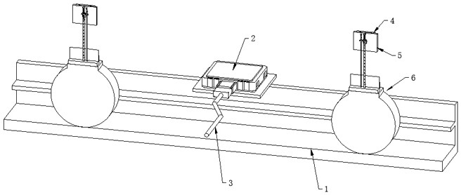
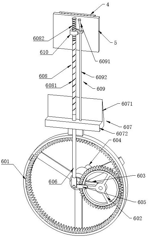
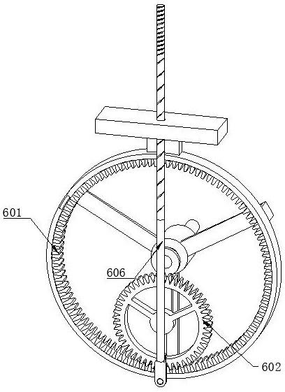
[0030] like Figures 1 to 6 As shown, the angle-adjustable monitoring device based on millimeter-wave radar includes a millimeter-wave radar main body 2 mounted on a vehicle frame 1. The millimeter-wave radar main body 2 is connected to the information processing unit through a wire 3, and also includes a number of The wireless signal antenna 4 matched with the radar body 2, the wireless signal antenna 4 moves with the up and down movement of the longitudinal movable rod 606, and the wireless signal antenna 4 is horizontally deflected with a vertical straight line as the axis when it moves to the upper vertex, and the wireless signal antenna 4 moves When reaching the lower apex, a longitudinal flip occurs with a horizontal straight line as the axis, wherein the adjustment mechanism 6 includes an outer fixed ring 601, an inner rotating gear 602, a driving crank 603, a driving center shaft 604...


PUM


Abstract

The invention relates to the technical field of radar, in particular to an angle-adjustable monitoring device and method based on a millimeter-wave radar, comprising a millimeter-wave radar main body mounted on a vehicle frame, the millimeter-wave radar main body being connected to an information processing part through a wire, and further comprising: It includes several wireless signal antennas that cooperate with the main body of the millimeter-wave radar. The wireless signal antennas move with the up and down movement of the longitudinal movable rod. When the wireless signal antenna moves to the lower vertex, the vertical flip occurs with the horizontal straight line as the axis; the position of the wireless signal antenna is changed by the adjustment mechanism, which can realize the transmission of the wireless signal in the vertical direction while realizing the plane angular resolution. It is convenient to realize the judgment of the target height information through the wireless signal data in the vertical direction, thereby reducing the possibility of accidents.

Description

technical field [0001] The invention relates to the technical field of radar, in particular to an angle-adjustable monitoring device and method based on a millimeter-wave radar. Background technique [0002] Millimeter wave radar is a radar that works in the millimeter wave band. Usually, the millimeter wave refers to the frequency domain of 30 to 300 GHz (wavelength is 1 to 10 mm). The wavelength of millimeter wave is between microwave and centimeter wave. Therefore, millimeter wave radar has some advantages of microwave radar and photoelectric radar. Compared with sensor technologies such as lidar, it has the characteristics of all-weather detection in rain and snow, and has a great advantage in the automotive field. Wide range of applications, such as Tesla's automatic driving based on millimeter-wave radar, Baidu Auto's automatic driving based on high-precision maps, millimeter-wave radar and vision, Honda and other brands based on millimeter-wave radar to achieve assist...

Claims


Application Information

Patent Timeline
Patent Type & Authority Patents(China)
IPC IPC(8): H01Q3/02H01Q1/32H01Q1/22G01S13/88G01S13/08G01S7/02
CPCH01Q3/02H01Q1/225H01Q1/3233G01S13/882G01S13/08G01S7/02
Inventor 陈韬黎桂新林锦夏肖玲莉
Owner 深圳市国天电子股份有限公司
Learn More