
Heat dissipation lighting device

A lighting device and mounting board technology, applied in the field of lighting, can solve problems such as poor exhaust effect, low space utilization rate, and large wind resistance, and achieve the effect of protecting the motor and exhaust fan blades and high space utilization rate

Active Publication Date: 2019-03-01
东莞市闻誉实业有限公司
View PDF5 Cites 0 Cited by
  • Summary
  • Abstract
  • Description
  • Claims
  • Application Information

AI Technical Summary

Problems solved by technology

[0002] At present, in some places, for example, an exhaust fan needs to be installed in the bathroom to achieve the effect of exhausting exhaust gas. Traditional exhaust fans are installed on the ceiling or wall, and the fan blades of the exhaust fan are installed A mesh dust cover, in order to increase the exhaust volume and reduce the wind resistance, generally, the mesh of the dust cover is relatively large, that is, if the mesh of the dust cover is too small, it is easy to cause excessive wind resistance and poor exhaust effect This leads to the fact that the mesh of the dust cover of the exhaust fan needs to have a certain size to increase the exhaust volume and reduce wind resistance. When children poke the dust cover with sharp objects out of curiosity, it is easy to pass through Dust cover, causing the spikes to come into contact with the rotating blades on the exhaust fan, creating a safety hazard, i.e. poor safety
[0003] Furthermore, in these places, for example, lamps need to be installed in the bathroom for lighting effects, and installing exhaust fans and lamps separately will result in low space utilization, that is, occupying a large space

Method used


Image

  • Heat dissipation lighting device
  • Heat dissipation lighting device
  • Heat dissipation lighting device

Examples


Embodiment Construction

[0025] In order to facilitate the understanding of the present invention, the present invention will be described more fully below with reference to the associated drawings. Preferred embodiments of the invention are shown in the accompanying drawings. However, the present invention can be embodied in many different forms and is not limited to the embodiments described herein. On the contrary, the purpose of providing these embodiments is to make the disclosure of the present invention more thorough and comprehensive.

[0026] It should be noted that when an element is referred to as being “fixed” to another element, it can be directly on the other element or there can also be an intervening element. When an element is referred to as being "connected to" another element, it can be directly connected to the other element or intervening elements may also be present. The terms "vertical," "horizontal," "left," "right," and similar expressions are used herein for purposes of ill...


PUM


Abstract

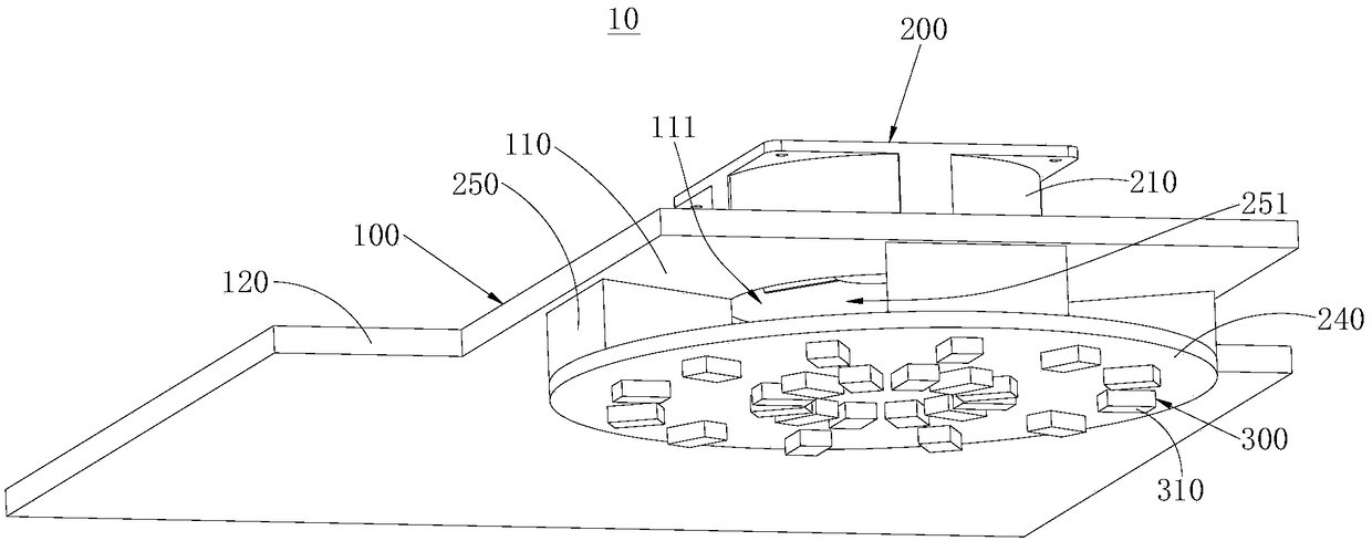
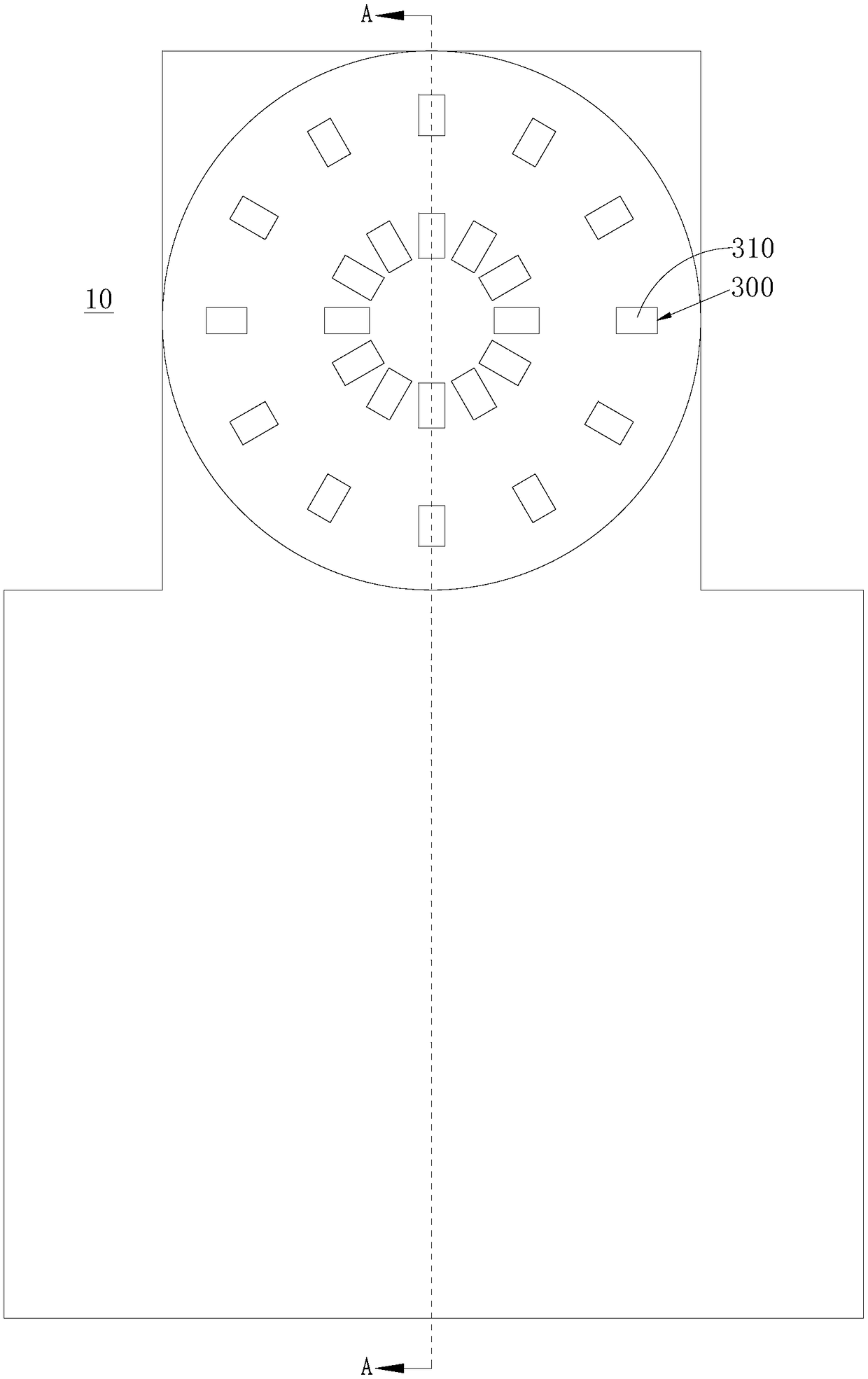
The invention discloses a heat dissipation lighting device which comprises an installing base, an air exhaust assembly, an LED assembly and a light emitting assembly. The installing base comprises an installing plate and a line passing plate, and an air inlet is formed in the installing plate; the air exhaust assembly comprises an outer frame, a motor, air exhaust fan blades, a lamp board and multiple partition blocks, the air exhaust fan blades are arranged to face the air inlet, an air inlet channel is formed between every two adjacent partition blocks, and all the air inlet channels communicate with the air inlet separately; the LED assembly comprises multiple LED lamp beads; the light emitting assembly comprises a fastening ring and a light emitting cover body, a clamping groove is formed in the edge of the side of the lamp board, a clamping strip is arranged on the inner side wall of the fastening ring, the fastening ring is arranged outside the edge of the side of the lamp board in a sleeving mode, and the clamping strip is embedded into the clamping groove. According to the heat dissipation lighting device, the lamp board can shield the air inlet to achieve the effect of protecting the motor and the air exhaust fan blades, and therefore the safety is higher; in addition, the air inlet channels are formed through the partition blocks and the lamp board, and then an air exhaust effect is achieved.

Description

technical field [0001] The invention relates to the technical field of lighting, in particular to a heat dissipation lighting device. Background technique [0002] At present, in some places, for example, an exhaust fan needs to be installed in the bathroom to achieve the effect of exhausting exhaust gas. Traditional exhaust fans are installed on the ceiling or wall, and the fan blades of the exhaust fan are installed A mesh dust cover, in order to increase the exhaust volume and reduce the wind resistance, generally, the mesh of the dust cover is relatively large, that is, if the mesh of the dust cover is too small, it is easy to cause excessive wind resistance and poor exhaust effect This leads to the fact that the mesh of the dust cover of the exhaust fan needs to have a certain size to increase the exhaust volume and reduce wind resistance. When children poke the dust cover with sharp objects out of curiosity, it is easy to pass through The dust cover causes the pointed...

Claims


Application Information

Patent Timeline
Patent Type & Authority Patents(China)
IPC IPC(8): F21S8/00F21S8/04F21V17/16F21V19/00F21V33/00F24F13/078F21Y115/10
CPCF21S8/033F21S8/04F21V17/164F21V19/001F21V33/0096F24F13/078F24F2221/02
Inventor 叶伟炳
Owner 东莞市闻誉实业有限公司
Learn More