Tilting wing UAV with an aerodynamic layout and tilting mechanism

A technology of tilting mechanism and tilting wings, applied in the field of unmanned aerial vehicles, can solve the problems of fast flight speed, high take-off site requirements, slow cruising speed, etc., and achieve the effects of long battery life, high force-to-efficiency ratio and high efficiency

Active Publication Date: 2019-01-11
昆山鲲鹏无人机科技有限公司 +1
View PDF5 Cites 0 Cited by
  • Summary
  • Abstract
  • Description
  • Claims
  • Application Information

AI Technical Summary

Problems solved by technology

Due to the fast flight speed of fixed-wing UAVs, high requirements for take-off sites and high operational technical requirements, it is not suitable for engineers who are new to UAVs. For low-level reasons, the function of single take-off and large-scale operation cannot be realized
[0003] Because the front and rear wings of traditional tilting wing drones are at the same level in fixed wing mode, the rear wing is easily affected by the airflow of the front wing, which reduces the efficiency of the wing surface, and the rear wing is prone to tremors, resulting in Overall poor flying experience
[0004] Due to the symmetrical installation of two pairs of power units at the front and rear of traditional tilt-rotor UAVs, the rear power unit is greatly affected by the airflow of the front power unit, which reduces the efficiency of the rear power unit and is prone to tremors
[0005] The traditional tilt-rotor UAV uses a linkage mechanism to rotate the shafts of the front and rear two pairs of tiltable wings, which makes it difficult to calibrate the inclination angle of the front and rear wings, and the control flexibility is not good. The front and rear wings cannot be tilted independently, and maintenance is troublesome , and the connecting rod used by the connecting mechanism of the front and rear wing tilting mechanism occupies a large space inside the fuselage, which is not conducive to the full utilization of the space inside the drone fuselage

Method used


Image

  • Tilting wing UAV with an aerodynamic layout and tilting mechanism
  • Tilting wing UAV with an aerodynamic layout and tilting mechanism
  • Tilting wing UAV with an aerodynamic layout and tilting mechanism

Examples


Embodiment Construction

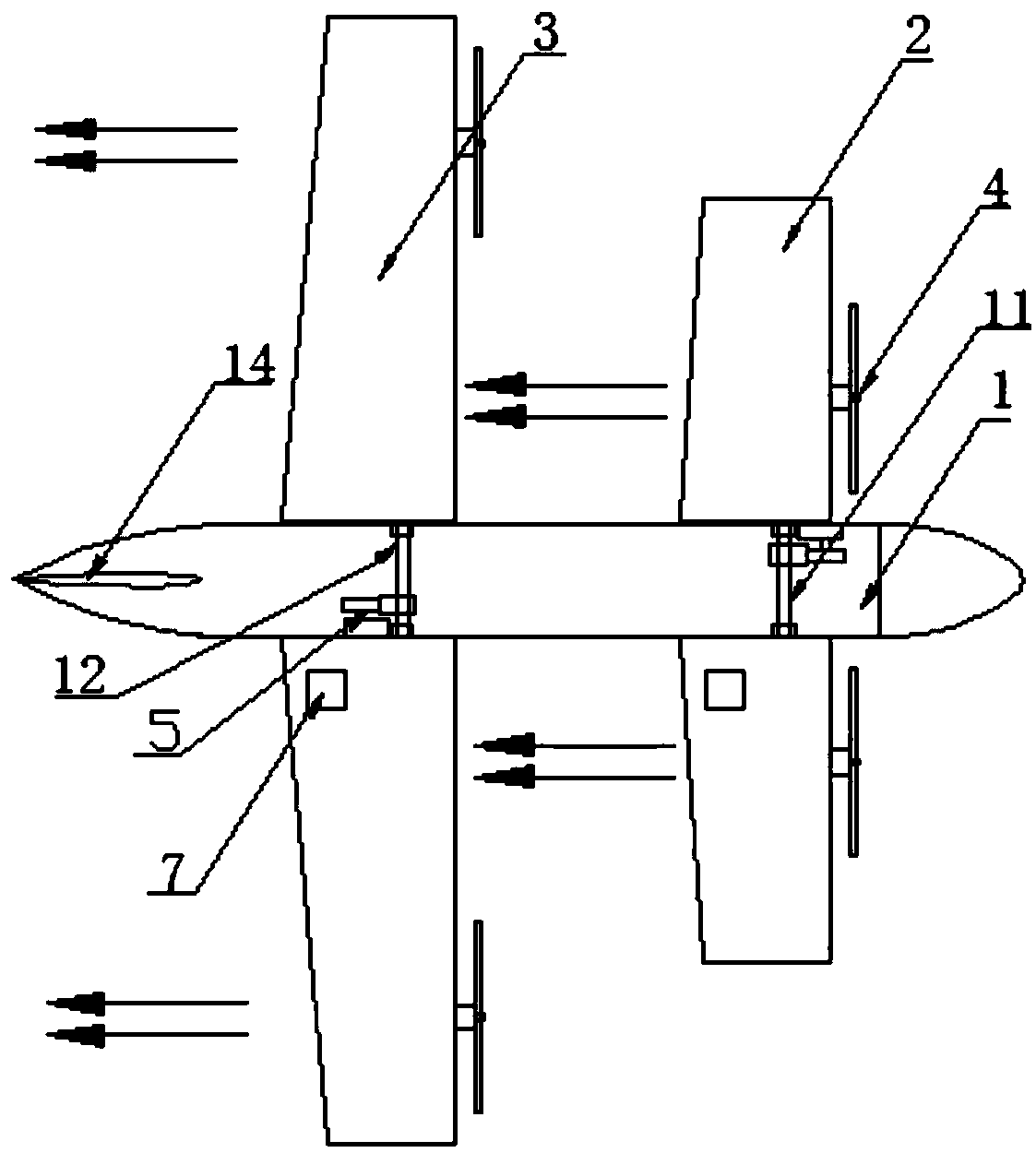
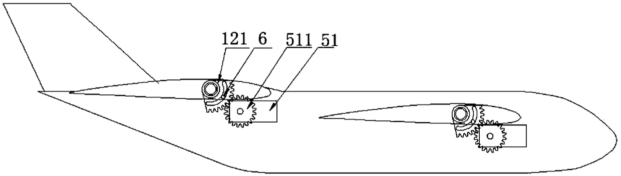
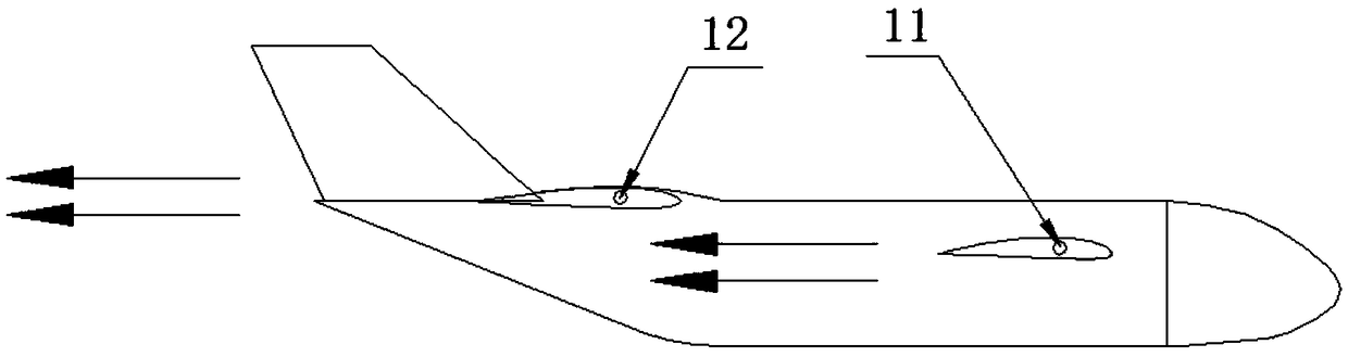
[0024] Aiming at the above-mentioned technical solution, a preferred embodiment is given and described in detail with reference to the drawings. see Figure 1 to Figure 5 , the present invention includes a fuselage, a front wing, a rear wing, a propeller power unit, a tilting mechanism, wherein.

[0025] Before and after the fuselage 1, a front rotating shaft 11 and a rear rotating shaft 12 are installed, and the front rotating shaft and the rear rotating shaft run through the fuselage transversely respectively, so that the two ends of the front and rear rotating shafts are respectively located at both sides of the fuselage. Both sides in the fuselage where front and rear rotating shafts are provided with support bearing housing 13, are used for supporting front rotating shaft and rear rotating shaft, make front rotating shaft and rear rotating shaft can rotate under the support of bearing housing. In the fuselage, the installation height of the front rotating shaft is lower ...


PUM


Abstract

The invention discloses a tilting wing unmanned aerial vehicle with an aerodynamic layout and a tilting mechanism, including a fuselage, and front and rear wings installed on the fuselage, and is characterized in that the front and rear wings are equipped with front and rear wings with staggered positions. Power device; rotatable tilting shafts are respectively installed at the front and rear positions of the fuselage, the front and rear tilting shafts run through the fuselage, and the front and rear wings are respectively fixed at both ends of the front and rear tilting shafts; The front and rear shafts in the fuselage are respectively provided with tilting mechanisms for driving the front and rear wings to rotate. At the same time, it is possible to detect whether the wings are loose through the set wing angle sensor. Compared with the tilting-wing unmanned aerial vehicle with traditional layout, the present invention can significantly improve the aerodynamic efficiency and flight performance of the aircraft in fixed-wing mode, and has great application value.

Description

technical field [0001] The invention relates to an unmanned aerial vehicle, in particular to a tilting-wing unmanned aerial vehicle capable of vertical take-off and landing with an optimized aerodynamic layout and an optimized tilting mechanism. technical background [0002] At present, small civil UAVs can be roughly divided into two types: fixed-wing UAVs and multi-rotor UAVs. Fixed-wing UAVs have long battery life, high flight energy efficiency ratio, and fast flight speed. With the advantage of high efficiency, the multi-rotor drone has the functions of hovering in the air, realizing fixed-point observation, and vertical take-off and landing. Due to the fast flight speed of fixed-wing UAVs, high requirements for take-off sites and high operational technical requirements, it is not suitable for engineers who are new to UAVs. For low-level reasons, the function of single take-off and large-scale operation cannot be realized. [0003] Because the front and rear wings of t...

Claims


Application Information

Patent Timeline
Patent Type & Authority Patents(China)
IPC IPC(8): B64C3/38B64C29/00
CPCB64C3/38B64C29/0008B64F5/60B64U30/10B64U30/20
Inventor 李袁杰刘其民岳友飞
Owner 昆山鲲鹏无人机科技有限公司
Why Eureka
Try Eureka