
flapping wing for orthopter

The invention relates to a flapping wing and flapping aircraft technology, which is applied to the flapping wing of the flapping aircraft. In the field, it can solve the problems that affect the flight performance of flapping wings, do not have controllable active deformation capabilities, and cannot be practical.

Inactive Publication Date: 2020-11-13
西北工业大学太仓长三角研究院 +1
View PDF6 Cites 0 Cited by
  • Summary
  • Abstract
  • Description
  • Claims
  • Application Information

AI Technical Summary

Problems solved by technology

However, most of the existing flapping wings do not have controllable active deformation capabilities, and the existing flapping wings cannot perform fine active and controllable deformations, and it is currently impossible to design flapping wings that can actively and complexly deform according to traditional mechanical design methods. Moving wings, or even if designed, the volume and mass are too large to be practical, thus affecting the flight performance of flapping wings

Method used


Image

  • flapping wing for orthopter
  • flapping wing for orthopter
  • flapping wing for orthopter

Examples


Embodiment Construction

[0018] The present invention will be further described in detail below in conjunction with the accompanying drawings and specific embodiments.

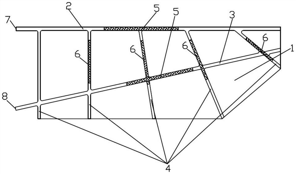
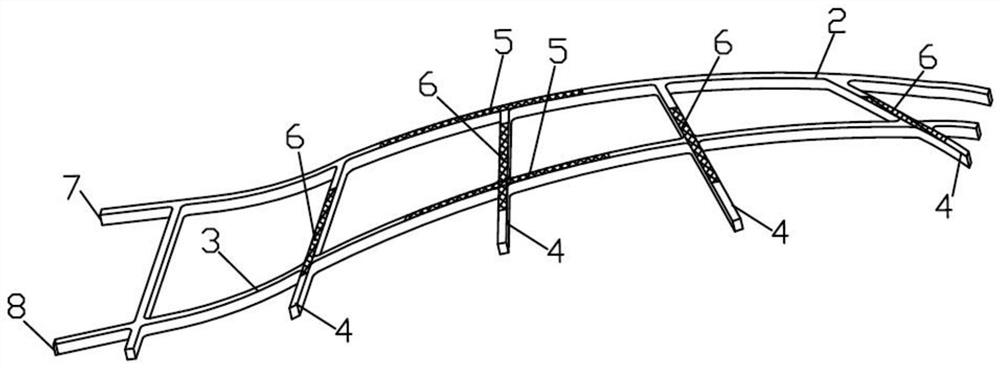
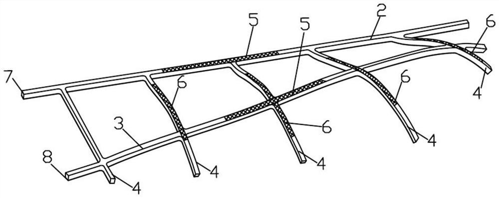
[0019] Depend on Figure 1~4 It can be seen from the illustrated embodiment that this embodiment includes a skin 1 and a flapping wing skeleton formed by a plurality of skin support beams arranged and fixed together in the shape of a flapping wing, and the skin 1 is bonded to the flapping wing skeleton , so that the skin 1 is supported by the flapping wing skeleton to form a flapping wing, the flapping wing skeleton is a bionic flapping wing skeleton, and the bionic flapping wing skeleton has a spanwise bending deformation structure and a chordwise twisting deformation structure , the skin supporting beams that make up the skeleton of the bionic fluttering wing are strip-shaped materials with elasticity and easy deformation, including a main beam 2, an auxiliary beam 3 and multiple rib beams 4, and the skin 1 supported by the main bea...


PUM


Abstract

The invention discloses a fluttering wing for an ornithopter, and belongs to the technical field of ornithopters. A fluttering wing framework is a bionic fluttering wing framework, the bionic fluttering wing framework comprises a wingspan-direction bending deformation structure and a wing-chord-direction distortion structure, and all skin supporting beams forming the bionic fluttering wing framework are made from elastic and deformable strip-shaped materials and comprise the main beam, the auxiliary beam and a plurality of wing rib beams; the skin part supported by the main beam forms a frontedge of the fluttering wing, the auxiliary beam is located behind the main beam, the wing rib beams are uniformly arranged in the wingspan direction, the main beam and the auxiliary beam are fixed together, and the skin part supported by the back ends of the wing rib beams forms a back edge of the fluttering wing; bent wingspan-direction piezoelectric fiber pieces respectively adhere to the main beam part and auxiliary beam part of the fluttering wing; distorted wing-chord-direction piezoelectric fiber pieces respectively adhere to all wing rib beam parts or partial wing rib beam parts of thefluttering wing. The fluttering wing has the advantages of being low in mass, flexible, efficient in flight and the like.

Description

technical field [0001] The invention relates to a flapping aircraft, in particular to a flapping wing for the flapping aircraft. Background technique [0002] The bionic flight of the flapping wing aircraft has a wide range of application prospects in national defense and military affairs, and has become the focus of research by various countries. In nature, birds control flight by controlling the flapping and deformation of wings. Birds actively adjust the deformation of wings according to different flight purposes to generate corresponding aerodynamic force, so that the flight is in the best flight state. Studies have shown that the aerodynamic force required by the bird-like aircraft is different under different flight conditions, so it is necessary for the flapping wings to produce controllable deformation according to the corresponding flight conditions to improve the efficiency and maneuverability of the flight. However, most of the existing fluttering wings do not ha...

Claims


Application Information

Patent Timeline
Patent Type & Authority Patents(China)
IPC IPC(8): B64C33/02
Inventor 宣建林马东福包晗年鹏梁少然杨文青李育斌宋笔锋
Owner 西北工业大学太仓长三角研究院
Learn More