A building suspended ceiling structure that can shorten the distance from the ceiling

A ceiling and architectural technology, applied in the direction of building components, building structures, buildings, etc., can solve problems such as complex structures and inappropriateness, and achieve the effects of firm structure, reduced distance, and convenient adjustment

Active Publication Date: 2020-04-10
GUANGZHOU SHANGMAC CO LTD
View PDF9 Cites 0 Cited by
  • Summary
  • Abstract
  • Description
  • Claims
  • Application Information

AI Technical Summary

Problems solved by technology

[0003] The technical problem of this snap-tooth keel ceiling structure is that the structure is complex, and the existence of the suspender 7 and the main keel 4 lengthens the distance between the gusset 6 and the ceiling, so this kind of ceiling structure is generally only suitable for buildings with a higher floor height. For the room, because the length of the light suspender is more than 20 centimeters, for the existing residence, the general floor height is only 2.9 meters. It is obviously inappropriate to adopt this kind of ceiling structure

Method used


Image

  • A building suspended ceiling structure that can shorten the distance from the ceiling
  • A building suspended ceiling structure that can shorten the distance from the ceiling
  • A building suspended ceiling structure that can shorten the distance from the ceiling

Examples


Embodiment 1

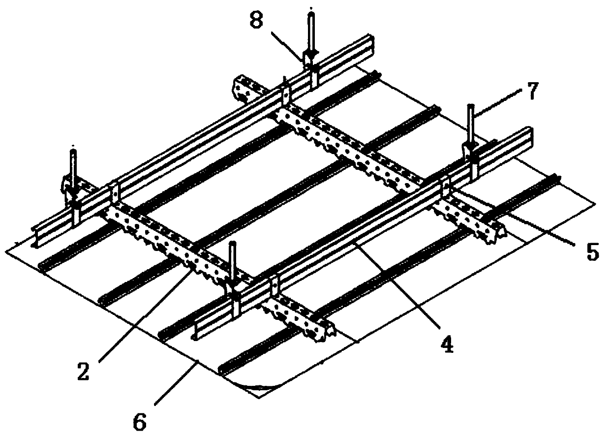
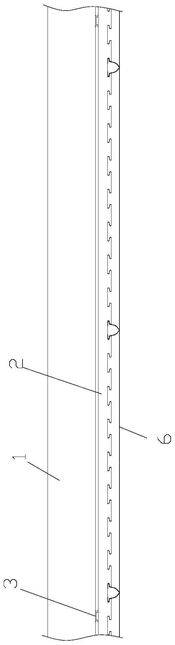
[0051] Such as figure 2 As shown, the building ceiling structure described in this embodiment can shorten the distance from the ceiling, and the building ceiling structure can shorten the distance from the ceiling. Mounting hole 11, said mounting hole 11 is provided with a wall body connector 3, said snap-tooth keel 2 is installed on the ceiling 1 through the wall body connector 3, and pinch plate 6 is installed on the bottom surface of snap-tooth keel 2, its Features:

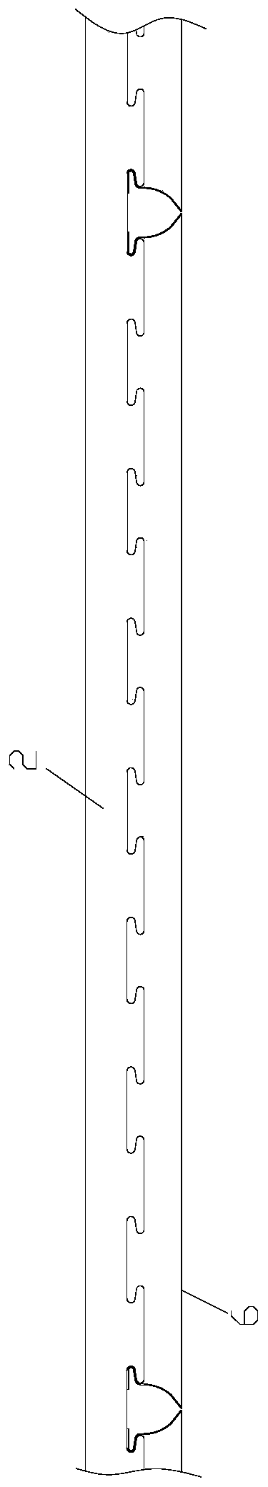
[0052] Such as image 3 , 4 , 5, the snap-tooth keel 2 is composed of a top surface 22 and two front and rear sides 23 connected together, the top surface 22 is provided with round holes 21 at intervals, and the bottom edge of the side surfaces 23 is provided with intervals There is a card slot 24; the edges of both sides of the buckle plate 6 are provided with upper flanges 62, and the top of the upper flange 62 has a snap-in portion 61 that can be snapped into the card slot 24, and the two adjacent buckl...


PUM


Abstract

The invention discloses a building ceiling structure capable of shortening distance between pinch plates and a ceiling. The building ceiling structure includes a plurality of latch keels; the latch keels are arranged on the ceiling through wall connection members; and pinch plates are arranged on bottom surfaces of the latch keels. The building ceiling structure is characterized in that each latch keel includes a top surface, a front side surface and a back side surface which are connected together; holes are formed in the top surfaces at intervals; clamping grooves are formed in bottom edges of the side surfaces; upper turn-ups are arranged two side edges of each pinch plate; snap-in portions are arranged on the tops of the upper turn-ups; and the snap-in portions of two adjacent pinch plates are snapped in the same clamping groove in a mirror image shape. The advantages of the invention are that the wall connection members are embedded in the ceiling, and then the distance between the ceiling and the pinch plates can be shortened obviously; compared with the prior art, the distance between hanging rods and a main keel can be avoided; the wall connection members have a height adjustment function and a tightening function, and then the building ceiling structure is firm, is easy to install, and is suitable for houses with the height of 2.9 meters in china.

Description

technical field [0001] The invention relates to a building suspended ceiling structure, in particular to a building suspended ceiling structure which can shorten the distance from the ceiling. Background technique [0002] Existing building ceilings generally use suspended ceilings to make them more beautiful or to achieve corresponding functions. figure 1 Shown is an existing ceiling structure, which adopts snap-tooth keel 2 to install pinch plate 6, which mainly includes boom 7, main keel hanger 8, main keel 4, snap-tooth keel hanger 5, clip Teeth keel 2 and buckle plate 6; the top of suspender 7 is connected with the expansion screw installed on the ceiling through the connecting piece, suspender 7 is connected with main keel 4 through main keel hanger 8, and snap-tooth keel 2 is suspended by snap-tooth keel Part 5 is connected on the main keel 2, and the buckle plate 6 is clamped on the bayonet keel 2. Among them, the function of the boom 7 is to connect and adjust the...

Claims


Application Information

Patent Timeline
Patent Type & Authority Patents(China)
IPC IPC(8): E04B9/06E04B9/22
CPCE04B9/06E04B9/22
Inventor 陈孔杰
Owner GUANGZHOU SHANGMAC CO LTD
Why Eureka
Try Eureka