Supercharge Your Innovation With Domain-Expert AI Agents!

Multifocal spot imaging system

An imaging system and multi-focal spot technology, applied in the field of multi-focal spot imaging systems, can solve problems such as non-uniform noise distribution, unbalanced X-ray flux, etc.

Active Publication Date: 2020-08-11
KONINKLJIJKE PHILIPS NV
View PDF6 Cites 0 Cited by
  • Summary
  • Abstract
  • Description
  • Claims
  • Application Information

AI Technical Summary

Problems solved by technology

As a result of the above, the pre-patient radiation beam filter 1100 is not well suited to a particular angle, object and / or scan, and, unfortunately, can lead to unbalanced x-ray flux and non-uniform noise distribution

Method used


Image

  • Multifocal spot imaging system
  • Multifocal spot imaging system
  • Multifocal spot imaging system

Examples


Embodiment Construction

[0032] It should be appreciated that the use of sequence numbers (ie, first, second, . . . ) hereinafter indicates an order of introduction of elements described herein, but does not describe the elements. Accordingly, the terms "first" and "second" relative to the term "focal spot" (and / or other elements) refer only to the order in which the focal spots are introduced and described herein.

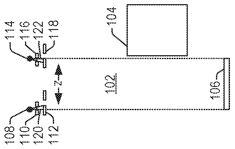
[0033] initial reference Figure 14 , schematically illustrates an example imaging system 1400, such as a computed tomography (CT) scanner. Imaging system 1400 includes a generally stationary gantry 1402 and an angularly rotating gantry 1404 . Rotating gantry 1404 is rotatably supported by stationary gantry 1402 and rotates about an examination region 1406 about a longitudinal or z-axis ("Z"). The one-dimensional or two-dimensional radiation-sensitive detector array 1408 includes multiple rows of detectors extending along the z-axis direction, and each row includes a plurality of detecto...


PUM


Abstract

An imaging system (1400) includes a first focal spot (1410 1 ) and the second focal spot (1410 N ), a first pre-patient radiation beam filter having a first profile disposed between the first focal spot and the examination region (1416 1 ) and a second pre-patient radiation beam filter having a second profile disposed between the second focal spot and the examination region (1416 N ), and a source controller (1412), the source controller is based on at least one of the angular position of the focal spot, the shape of the region of interest of the scanned object or target, or both based on the scanned object or target. The operation of the focus spot is controlled by modulating the operation during scanning by changing the size between adjacent regions.

Description

technical field [0001] The following generally refers to multi-focal spot imaging systems and is described with particular focus on stereotube computed tomography (CT) imaging systems; however, the following also applies to single X-ray tube CT imaging systems with multiple focal spots. Background technique [0002] Stereotube computed tomography (CT) scanners include two focal spots that alternately emit ionizing X-ray radiation that passes through the examination region and parts of the object or target therein. In one example, the two focal spots are each part of a different X-ray tube positioned at the same angle with respect to the gantry bore, but at different z-axis positions. [0003] A different source collimator is used for each focal spot and a different pre-patient radiation beam filter is placed between each focal spot and each source collimator (e.g. in the beam section of the X-ray tube middle). A detector array detects radiation passing through the examinat...

Claims


Application Information

Patent Timeline
Patent Type & Authority Patents(China)
IPC IPC(8): A61B6/03
CPCA61B6/032A61B6/4007A61B6/4035A61B6/06A61B6/4021
Inventor T·克勒R·普罗克绍
Owner KONINKLJIJKE PHILIPS NV
Features
  • R&D
  • Intellectual Property
  • Life Sciences
  • Materials
  • Tech Scout
  • Unparalleled Data Quality
  • Higher Quality Content
  • 60% Fewer Hallucinations
Learn More