Wire take-up device for non-binding steel stranded wire

A wire take-up device and a technology for steel strands, which are applied in rope-making auxiliary devices, textiles and papermaking, textile cables, etc., can solve problems such as affecting steel strands, damage, and failure to remove steel strand coils smoothly, and achieve The effect of easy removal

Inactive Publication Date: 2017-03-29
浙锚科技股份有限公司
View PDF9 Cites 6 Cited by
  • Summary
  • Abstract
  • Description
  • Claims
  • Application Information

AI Technical Summary

Problems solved by technology

[0004] The invention solves the defect that the steel strand coil cannot be removed smoothly due to the large frictional force generated between the fixed inner diameter fixed column and the steel strand coil in the prior art, and provides a non-bonding steel strand take-up device , the inner diameter column and the turntable are hinged, the top of the inner diameter column is radially supported by the radial rod, as long as the radial rod is removed, the inner diameter column and the turntable can be rotated, so that the inner diameter column and the steel strand reel The inner surface is separated to facilitate the removal of the steel strand coil
[0005] The invention also solves the defects in the prior art that when the steel strand reel is removed from the wire take-up device, it is easy to damage the PE extruded casing on the surface of the steel strand reel due to a relatively large external force, which affects the quality of the steel strand. Provide a non-bonded steel strand take-up device, the inner diameter column and the turntable are hinged, the top of the inner diameter column is radially supported by the radial rod, as long as the radial rod is removed, the inner diameter column and the turntable Rotation occurs, so that the inner diameter column is separated from the inner surface of the steel strand coil, which is convenient for the removal of the steel strand coil and will not damage the PE extrusion sleeve on the surface of the steel strand

Method used


Image

  • Wire take-up device for non-binding steel stranded wire
  • Wire take-up device for non-binding steel stranded wire
  • Wire take-up device for non-binding steel stranded wire

Examples


Embodiment

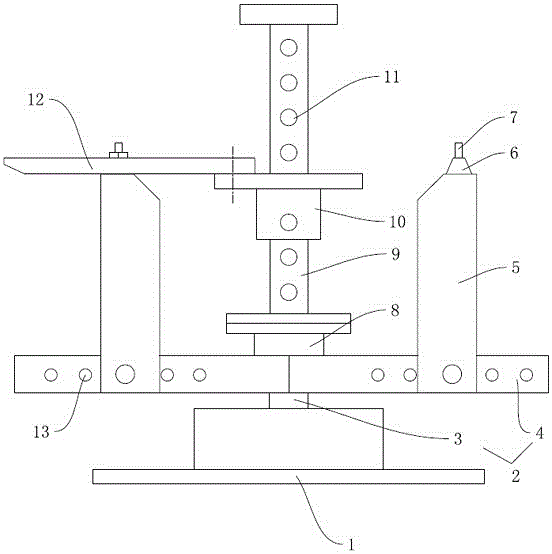
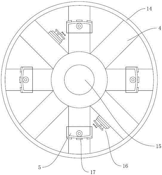
[0023] Embodiment: a kind of unbonded steel strand take-up device (referring to figure 1 figure 2 ), including a base 1 and a rotatable turntable 2 arranged on the base, the turntable includes a rotating shaft 3 and a support arm 4 radially fixed on the rotating shaft, and the outer ends of the supporting arms are connected by an outer ring 14 . In this embodiment, a total of 8 support arms are radially arranged, the lengths of the support arms are equal, the outer ring forms a circle, the cross section of the support arms is rectangular, and the upper surface of the support arms is fixed with pads. The support arm is provided with several radial adjustment holes 13 horizontally penetrating the side wall of the support arm, and the radial adjustment holes are arranged on the support arm along the length direction of the support arm.

[0024] The base is provided with a driving motor, the rotating shaft is connected with the driving motor, the driving motor drives the rotatin...


PUM


Abstract

The invention relates to a wire take-up device for a non-binding steel stranded wire. According to the wire take-up device, the defects in the prior art that a greater frictional force is generated between a fixed inner-diameter fixing post and a steel stranded wire disc, and the steel stranded wire disc cannot be smoothly taken down. The wire take-up device comprises a base and a rotating disk which is arranged on the base and can be rotated; an inner-diameter upright post is hinged to the rotating disk; a central post is arranged at the middle position of the rotating disk; a detachable radial rod is arranged between the upper end of the inner-diameter upright post and the central post. The inner-diameter upright post can rotate relative to the rotating disk; after the steel stranded wire is wound, the inner-diameter upright post rotates relative to the rotating disk and further can be separated from the inner diameter of the steel stranded wire disc, so that the taking of the steel stranded wire disc is facilitated; meanwhile, great force is not applied in a taking-out process, so the damage to a PE extrusion molding casing pipe on the surface of the steel stranded wire is avoided.

Description

technical field [0001] The invention relates to a wire take-up device, in particular to a wire take-up device for unbonded steel strands. Background technique [0002] Steel strands are the main force-bearing parts in the traction system. The steel strands used need to ensure integrity without any joints or breakpoints in the middle. Therefore, the length of each steel strand is relatively long, which makes the conveyor belt A certain trouble has come, so the existing steel strands are all stored and transported by being coiled into rolls. However, the rigidity and strength of the steel strand itself are relatively large, and it is relatively difficult to directly coil it into a coil, and a special take-up device is required for coiling. [0003] At present, the commonly used wire take-up devices generally include a rotatable turntable and a column arranged on the turntable. A plurality of columns form a circle, which is the position where the steel strand is wound, that is...

Claims


Application Information

Patent Timeline
Patent Type & Authority Applications(China)
IPC IPC(8): D07B7/10
CPCD07B7/10
Inventor 伍军周成顺胡菊云
Owner 浙锚科技股份有限公司
Why Eureka
Try Eureka