
Sound-light alarm device

An acousto-optic alarm device and optical sensor technology, applied in the direction of electric transmission signal system, etc., can solve the problems of insufficient warning force and easy failure of static warning signs, achieve great practical and popularization value, strong versatility, and increase the safety distance Effect

Pending Publication Date: 2017-03-29
STATE GRID CORP OF CHINA +2
View PDF0 Cites 2 Cited by
  • Summary
  • Abstract
  • Description
  • Claims
  • Application Information

AI Technical Summary

Problems solved by technology

In order to effectively remind people to prevent various safety accidents such as entering the electrified area, stepping into the air, and falling, most of the existing warning signs are static safety warning signs, such as enamel signs, reflective paint signs, and reflective film signs. Brands, etc.; enamel cards play a certain role in the daytime. Reflective paints are mostly painted with fluorescent powder to have a certain luminous effect, but they are prone to failure after a period of time. Reflective film signs are usually placed on poles and towers to prevent collisions and substation equipment nameplates However, in the face of a large number of people and electric workers who lack professional skills, the static warning signs are obviously insufficient in the on-site warning. Therefore, it is necessary to design an audible and visual alarm device to wake up in time by means of audible and visual reminders. personnel in the area, so as to avoid the occurrence of safety accidents

Method used


Image

  • Sound-light alarm device
  • Sound-light alarm device
  • Sound-light alarm device

Examples


Embodiment Construction

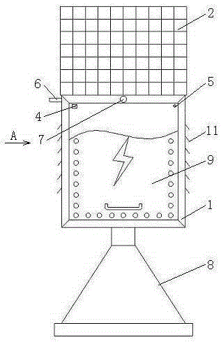
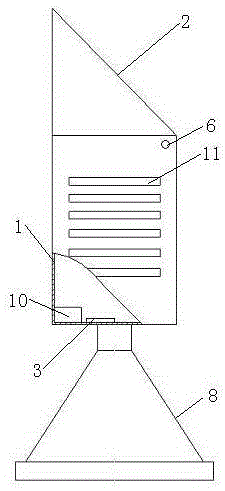
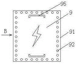
[0015] Refer to attached figure 1 , attached figure 2 , attached image 3 , attached Figure 4 , an audible and visual alarm device of the present invention, which consists of a housing 1, a solar panel 2, a controller 3, a data interface 4, a deck 5, a light sensor 6, a camera 7, a base 8, a sign 9, and a storage battery 10 Composition, a solar panel 2, a light sensor 6, and a camera 7 are respectively arranged on the casing 1; the controller 3, the data interface 4, and the battery 10 are respectively arranged in the casing 1; the casing 1 is connected to the base 8; the sign 9 Set on the housing 1 through the deck 5; the controller 3 is respectively connected with the solar panel 2, the data interface 4, the light sensor 6, and the storage battery 10; The multifunctional connection port for transmission; the light sensor 6 is a sensing device for sensing the light intensity of the place of use; the sign 9 is a sign with ultrasonic detection and sound and light reminder ...


PUM


Abstract

The invention relates to a sound-light alarm device. The sound-light alarm device is composed of a cabinet, a solar panel, a controller, a data interface, a clamping holder, a light sensor, a camera, a base, a sign board and a storage battery; the sign board is a sign board with an ultrasonic detection function and a sound-light prompting function; signs and prompting sound on the sign board are set according to use conditions; since the sound-light alarm device is provided with the data interface, connection between each part can be facilitated when the sign board is replaced; since the sound-light alarm device is provided with the light sensor, switching between sound prompting and light prompting is facilitated, and therefore, people will not be disturbed by the sound-light alarm device at night; since the sound-light alarm device is provided with the camera, the activities of people around the sound-light alarm device can be recorded in real time; since the sound-light alarm device is provided with an ultrasonic detection module, people passing the sound-light alarm device can be prompted to pay attention to safety at a long distance, and therefore, a safe distance is increased; the sign board can be replaced conveniently according to conditions, and therefore, the sound-light alarm device has high universality; and the sound-light alarm device is simple and convenient, and therefore, the sound-light alarm device has a high practical and promotion value.

Description

technical field [0001] The invention relates to a warning device, in particular to an audible and visual alarm device. Background technique [0002] After retrieving relevant patent documents, no acousto-optic alarm device with the same structure as the present invention has been retrieved yet. In order to effectively remind people to prevent various safety accidents such as entering electrified areas by mistake, preventing stepping into the air, and preventing falls, most of the existing warning signs are static safety warning signs, such as enamel signs, reflective paint signs, and reflective film signs. Brands, etc.; enamel cards play a certain role in the daytime. Reflective paints are mostly paints with phosphor powder added to have a certain luminous effect, but they are prone to failure after a period of time. Reflective film signs are usually placed on poles and towers to prevent collisions and substation equipment nameplates However, in the face of a large number o...

Claims


Application Information

Patent Timeline
IPC IPC(8): G08B7/06
CPCG08B7/06
Inventor 冯孝宏吉斌储亚男王生强任新宇夏艳林林毛春荣
Owner STATE GRID CORP OF CHINA
Learn More