Rapid chamfering device

A chamfering device and fast technology, applied in the field of parts processing, can solve the problems of low processing efficiency, difficult to meet precision requirements, and inflexible movement of processing tools, and achieve the effect of ensuring quality and improving processing efficiency and precision.

Inactive Publication Date: 2017-04-05
WUXI MINGZHU STEEL BALL
View PDF7 Cites 6 Cited by
  • Summary
  • Abstract
  • Description
  • Claims
  • Application Information

AI Technical Summary

Problems solved by technology

[0002] In the batch processing of mechanical parts, it is often necessary to chamfer the parts. The existing equipment used to process the chamfering of the parts has the disadvantage that the movement of the processing tool is not flexible enough, resulting in low processing efficiency and difficult to meet the precision requirements.

Method used


Image

  • Rapid chamfering device
  • Rapid chamfering device
  • Rapid chamfering device

Examples


Embodiment Construction

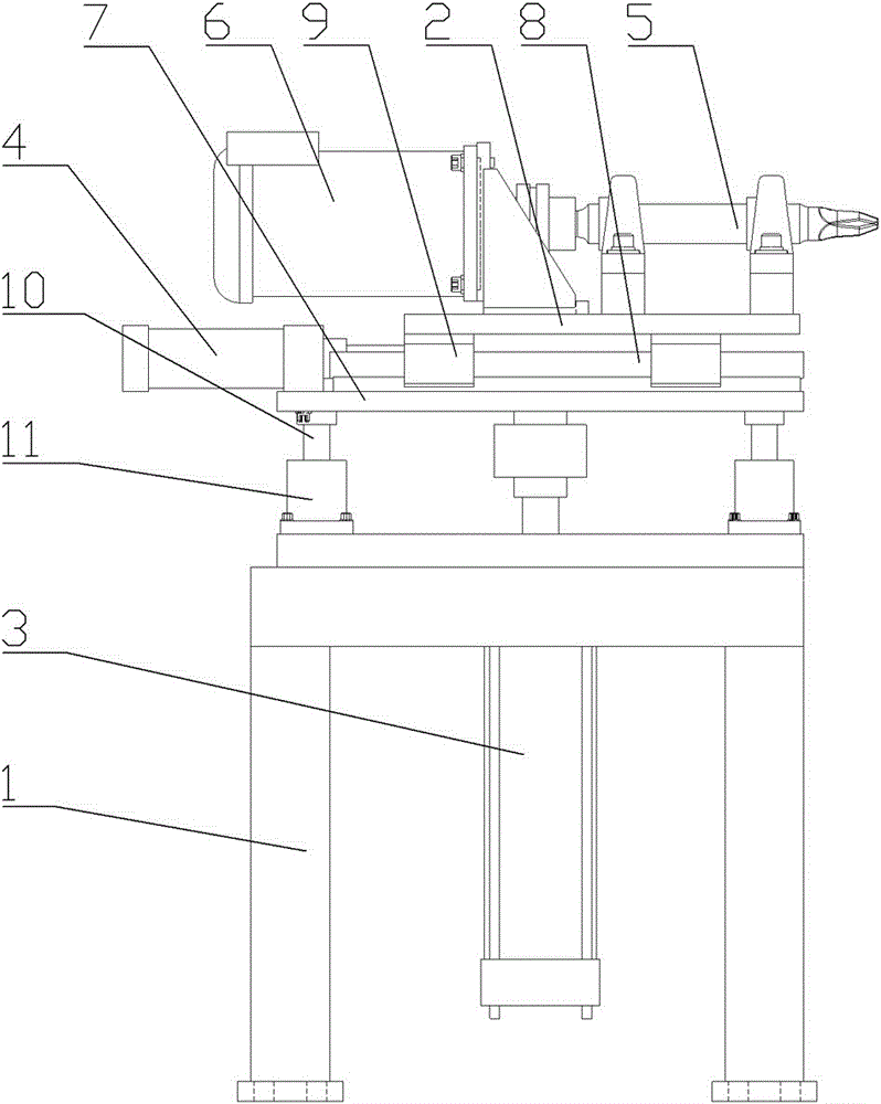
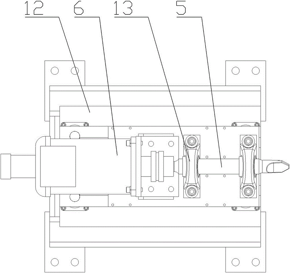
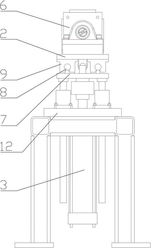
[0017] Such as Figure 1 to Figure 4 Middle: A fast chamfering device includes a frame 1, on which a moving mechanism is installed, the moving mechanism includes a moving seat 2, the moving seat 2 can move vertically through the lifting cylinder 3, and the moving seat 2 can move through the horizontal cylinder 4 can move in the horizontal direction, and rotating shaft 5 is installed on the moving seat 2, and one end of rotating shaft 5 is connected with motor 6, and the other end is connected with processing cutter (not drawing processing cutter among the figure). A lifting platform 7 is provided below the mobile seat 2, and a slide rail 8 is provided on the upper end of the lifting platform 7. There are two slide rails 8, and the two slide rails 8 are symmetrically arranged on both sides of the upper end of the lifting platform 7 along the horizontal direction. , the lower end of the mobile seat 2 is provided with a slider 9, and there are four sliders 9, and the four sliders...


PUM


Abstract

The invention provides a rapid chamfering device. The rapid chamfering device can enable a machining cutter to rapidly and flexibly move, the efficiency and the precision are high, and therefore the quality of chamfering of a machined part is ensured. The rapid chamfering device comprises a rack, and a travel mechanism is arranged on the rack. The rapid chamfering device is characterized in that the travel mechanism comprises a movable base, a lifting platform is arranged below the movable base, the bottom of the lifting platform is connected with a lifting air cylinder, a transverse air cylinder is arranged on the side portion of the lifting platform and connected with the movable base, sliding rails are arranged at the upper end of the lifting platform, sliding blocks are arranged at the lower end of the movable base, the movable base is connected to the sliding rails through the sliding blocks, the sliding blocks are in sliding fit with the sliding rails, the movable base is further provided with a rotating shaft, one end of the rotating shaft is connected with a motor, and the other end of the rotating shaft is connected with the machining cutter.

Description

technical field [0001] The invention relates to the technical field of parts processing, in particular to a fast chamfering device. Background technique [0002] In the batch processing of mechanical parts, it is often necessary to chamfer the parts. The existing equipment used to process the chamfering of the parts is not flexible enough to move the processing tool, resulting in low processing efficiency and difficult to meet the precision requirements. Contents of the invention [0003] In order to solve the problems in the prior art, the present invention provides a fast chamfering device, which can move the processing tool quickly and flexibly, with high efficiency and high precision, thereby ensuring the quality of the chamfering of the processed parts. [0004] A kind of quick chamfering device, it comprises frame, is equipped with moving mechanism on frame, it is characterized in that: described moving mechanism comprises moving seat, is provided with lifting platfo...

Claims


Application Information

Patent Timeline
Patent Type & Authority Applications(China)
IPC IPC(8): B23Q1/62B23Q5/26B23Q5/10
CPCB23Q1/621B23Q5/10B23Q5/26B23Q2705/102
Inventor 吴昊
Owner WUXI MINGZHU STEEL BALL
Why Eureka
Try Eureka