
Top drive cable saddle frame

A cable and saddle technology, which is applied in the field of top drive cable saddle frame, can solve the problems of potential safety hazards and inconvenient use of top drive cable saddle frame, and achieve the effects of reduced workload, reliable fixation and good flexibility

Inactive Publication Date: 2018-07-06
CHINA AVIATION OPTICAL-ELECTRICAL TECH CO LTD
View PDF7 Cites 0 Cited by
  • Summary
  • Abstract
  • Description
  • Claims
  • Application Information

AI Technical Summary

Problems solved by technology

[0005] The purpose of the present invention is to provide a top drive cable saddle frame to solve the problems of inconvenient use and potential safety hazards of the existing top drive cable saddle frame

Method used


Image

  • Top drive cable saddle frame
  • Top drive cable saddle frame
  • Top drive cable saddle frame

Examples


Embodiment Construction

[0025] The present invention will be further described below in conjunction with accompanying drawing.

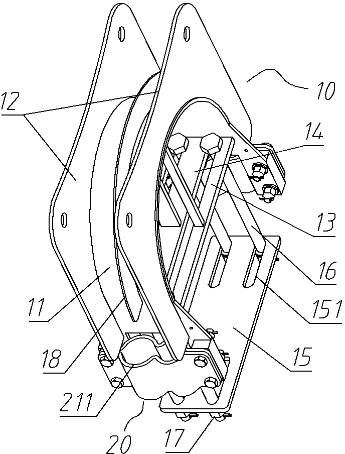
[0026] Embodiment 1 of the top drive cable saddle frame in the present invention is as Figure 3~Figure 6 Shown, comprise arched saddle seat 10, and saddle seat 10 comprises arched arc top plate 11 and is arranged on the cable baffle 12 of the width direction both sides of arc top plate 11, and arc top plate 11 and cable baffle plate 12 are welded Fixed into one body, forming the arched body of the saddle seat 10 .

[0027] A beam support plate 13 is connected between the two bottom ends of the saddle 10 to form a beam support seat for supporting on the upper beam surface of the derrick beam. A crossbeam clamping plate 15 spaced apart from the crossbeam support plate 13 is arranged below the crossbeam support plate 13 for supporting on the upper beam surface of the derrick crossbeam. The top drive cable saddle frame also includes four bolts 16 connected between the crossb...


PUM


Abstract

The invention relates to a top-drive cable saddle rack. The top-drive cable saddle rack comprises an arc saddle base, a crossbeam supporting seat is connected between two bottom ends of the saddle base, the top-drive cable saddle rack also comprises a U-shaped fixing rack whose opening is arranged towards the crossbeam supporting seat, the U-shaped fixing rack comprises a crossbeam clamping seat arranged with the crossbeam supporting seat at an interval and a vertical support-pull member connected between the crossbeam supporting seat and the crossbeam clamping seat, and at least one of the crossbeam supporting seat and the crossbeam clamping seat is connected with the vertical support-pull member through a thread fastening structure. The top-drive cable saddle rack can be supported on the upper beam surface of a derrick crossbeam through the crossbeam supporting seat, the crossbeam clamping seat can be supported on the lower beam surface of the derrick crossbeam, and detachable fixing of the saddle base on the derrick crossbeam can be realized through the vertical support-pull member and the thread fastening structure so that the fixing is more reliable, the flexibility is good, the cable can be directly taken down from the saddle base, the workload is reduced, the safety risk can be reduced, and the usage is convenient.

Description

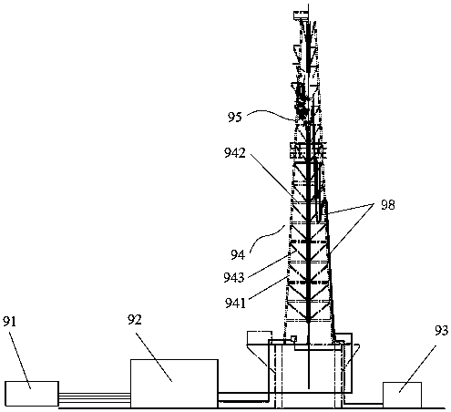
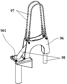
technical field [0001] The invention relates to a top drive cable saddle frame. Background technique [0002] Top drive drilling equipment is a new type of oil drilling machinery, a typical structure of which is as follows: Figure 1-Figure 2 As shown, it includes a generator set 91, an electric control room 92, a hydraulic station 93, a derrick 94 and a top drive device 95. The derrick 94 includes a column 941, a beam 942 and a cable tie 943. A special guide rail is provided inside the derrick 94, which can The upper part of the 94 space directly rotates the drill string, and sends it down along the special guide rail, and works at any height in the derrick 94 to complete many tasks such as drill string rotary drilling, drilling fluid circulation, single root connection, make-up and breakout, and back reaming. drilling operations. [0003] When the top drive device 95 works, it is necessary to connect the cable 98 and the hydraulic pipeline. Because the cable 98 is heavy a...

Claims


Application Information

Patent Timeline
Patent Type & Authority Patents(China)
IPC IPC(8): H02G3/02
CPCH02G3/0456
Inventor 王超
Owner CHINA AVIATION OPTICAL-ELECTRICAL TECH CO LTD
Learn More