Battery grid protection installation structure

A technology of installation structure and battery plate, applied in the direction of electrode carrier/current collector, etc., can solve problems such as poor use effect, and achieve the effects of good rotation performance, saving installation time, and good protection.

Inactive Publication Date: 2017-04-19
成都聚立汇信科技有限公司
View PDF4 Cites 4 Cited by
  • Summary
  • Abstract
  • Description
  • Claims
  • Application Information

AI Technical Summary

Problems solved by technology

Although the design of such a structure is reasonable, the effect of use is not good.

Method used


Image

  • Battery grid protection installation structure

Examples


Embodiment Construction

[0014] The present invention is described in further detail now in conjunction with accompanying drawing. These drawings are all simplified schematic diagrams, which only illustrate the basic structure of the present invention in a schematic manner, so they only show the configurations related to the present invention.

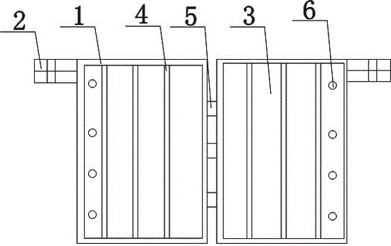
[0015] Such as figure 1 The preferred embodiment of the battery grid protective installation structure shown in the present invention includes a battery grid body 3, the surface of the battery grid body 3 is covered with a battery grid body shell 1, and the battery grid body shell 1 is detachably connected to the battery. On the grid body 3, there is a connecting end 2 of the battery grid body shell on the outside thereof, and the connecting end 2 of the battery grid body shell is integrally connected to the battery grid body shell 1, there are two battery grid bodies 3, and the battery grid body The main body 3 is provided with a support member 4, the suppor...


PUM


Abstract

The invention discloses a battery grid protection installation structure. The battery grid protection installation structure comprise two battery grid main bodies; the surface of each battery grid main body is coated with a battery grid main body shell; each battery grid main body shell is detachably connected with the corresponding battery grid main body; the outer side of each battery grid main body shell is provided with a battery grid main body shell connecting end; each battery grid main body shell connecting end is connected with the corresponding battery grid main body shell in an integrated manner; the battery grid main body shells of the two battery grid main bodies are connected via connecting shafts; and each battery grid main body is provided with more than one installation holes. The battery grid protection installation structure possesses excellent protection performance, is capable of avoiding scratches effectively, eliminating surface damage, and shortening installation time greatly, is high in connection strength, excellent in rotating performance, and higher in operating flexibility, and is convenient for installation.

Description

technical field [0001] The invention relates to an installation structure, in particular to a battery grid protection installation structure. Background technique [0002] As a power supply device that provides electric energy, batteries are widely used in daily life because they are easy to move, provide fixed current, and can be repeatedly charged and discharged. The battery grid is an important part of the inner plate of the lead-acid battery, and it is used in a large amount. The battery grid generally includes symmetrically distributed left and right grids, and each grid includes a plurality of thin straight ribs parallel to the long sides of the rectangular outer frame and There are thick straight ribs distributed at intervals in the middle of the thin straight ribs, and a plurality of radially distributed oblique ribs obliquely intersecting the thin straight ribs and the thick straight ribs. Although the design of such a structural mode is reasonable, the use effect...

Claims


Application Information

Patent Timeline
Patent Type & Authority Applications(China)
IPC IPC(8): H01M4/73H01M4/68
CPCH01M4/68H01M4/73Y02E60/10
Inventor 吕静
Owner 成都聚立汇信科技有限公司
Why Eureka
Try Eureka