Intraocular lens injector control system

A technology for intraocular lenses and syringes, which can be used in subcutaneous injection devices, intraocular lenses, prostheses, etc., and can solve problems such as annoying surgical preparation steps and failure to ensure good airtightness of the hydraulic transmission system

Inactive Publication Date: 2017-04-19
PHYSIOL
View PDF8 Cites 0 Cited by
  • Summary
  • Abstract
  • Description
  • Claims
  • Application Information

AI Technical Summary

Problems solved by technology

[0027] Unfortunately, devices from the prior art as described in document US 2011 / 0264102 A1 comprise major disadvantages: when making the connection between the syringe and the tubing system, for example The device does not ensure good airtightness of the hydraulic transmission system by its design
Very often, a purge step is necessary to remove unwanted air present in the hydraulic circuit, which makes surgical preparation steps particularly tedious

Method used


Image

  • Intraocular lens injector control system
  • Intraocular lens injector control system
  • Intraocular lens injector control system

Examples


Embodiment Construction

[0088] In this figure, identical or similar elements have the same reference numerals.

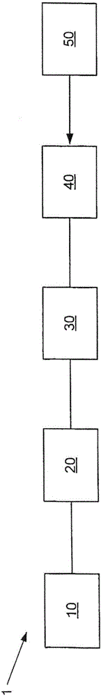
[0089] figure 1 A control device 1 for an intraocular lens injector 50 according to the invention is schematically shown.

[0090] Device 1 includes:

[0091] - a control module 10, which may for example be a control pedal;

[0092] - a support 40 arranged to accommodate an intraocular lens injector 50;

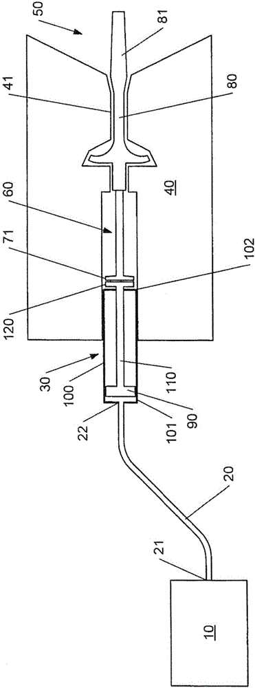
[0093] - the actuator 30 of the support 40, which is connected to the control module 10 by means of an airtight fluid transfer system 20, which actuator is arranged to communicate with an injector which may be an actuating device such as a moving piston system housed in a cylinder Part of 50 fits.

[0094] Optionally, the delivery system comprises several parts arranged to be interconnected and thereby form an airtight fluid hydraulic delivery system.

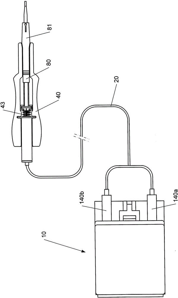
[0095] figure 2 is a schematic illustration of a variant of the control device 1 according to the invention, wherein the control ...


PUM


Abstract

A control device (1) for an intraocular lens injector (50) characterized in that the device comprises a support (40) arranged to accommodate a lens injector (50) which may be connected to a cartridge optionally pre-loaded with a lens, said support (40) comprising an actuator (30) connected to a fluid transmission system (20), said actuator (30) being arranged, as a result of the pressure force, to move between a first rest position and at least one second position.

Description

technical field [0001] The invention relates to a control device for controlling an intraocular lens injector. Background technique [0002] During surgery, an intraocular lens is used to replace the cloudy crystalline (natural) lens in cataract patients. Cataract surgery is probably the most common surgical procedure performed on humans, resulting in a significant improvement in vision in 98% of patients. [0003] Cataract surgical techniques have made tremendous progress over the past few years, especially due to the reduction in the size of the incision through which the artificial lens is implanted. New flexible materials (silicone, flexible acrylic, and hydrogel) allow the lens to pass through smaller incisions than those made with the first rigid polymethylmethacrylate (PMMA) implant. Due to the specific viscoelastic properties (shape memory) of flexible lenses, flexible lenses can be implanted in practically a folded or rolled configuration before regaining their or...

Claims


Application Information

Patent Timeline
Patent Type & Authority Applications(China)
IPC IPC(8): A61F2/16
CPCA61F2/1672A61F2/1678A61M5/14526A61F2/484
Inventor 费比安·卡奇阿兰·伍德特利克里斯多夫·帕纽利迪米特里亚·博祖科瓦
Owner PHYSIOL
Why Eureka
Try Eureka