
Brake system having a blending capability

A technology of braking equipment and braking circuit, applied in the direction of braking control system, braking safety system, braking transmission device, etc., can solve problems such as reducing braking power

Inactive Publication Date: 2017-04-19
AUDI AG
View PDF11 Cites 5 Cited by
  • Summary
  • Abstract
  • Description
  • Claims
  • Application Information

AI Technical Summary

Problems solved by technology

[0004] Now if in a hybrid vehicle in which for example the rear axle is driven electrically, the hybrid vehicle has hydraulic brakes known from the prior art (=> black / white distribution of the brake circuit, i.e. for the front and rear axle The separate brake circuit, which is supplied with hydraulic brake pressure by the brake master cylinder in a tandem configuration), obtains hydraulic fluid from the brake circuit assigned to the rear axle in order to reduce the braking power (pressure lowering), the floating piston of the brake master cylinder compensates for the above situation again, so that the rear axle is now overbraked due to the additional electric braking torque on the rear axle

Method used


Image

  • Brake system having a blending capability
  • Brake system having a blending capability

Examples


Embodiment Construction

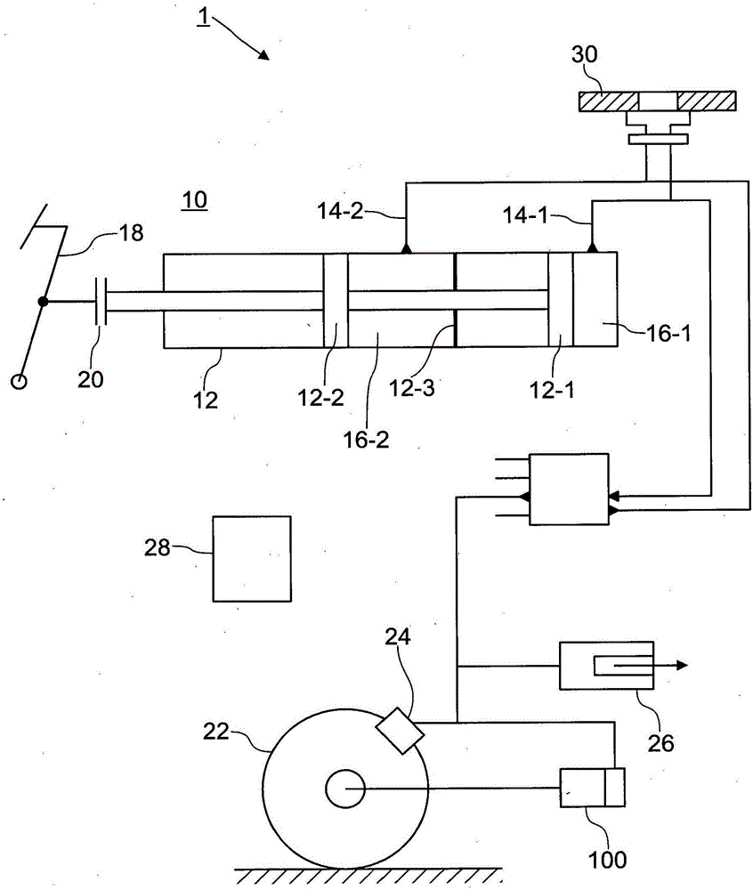
[0023] figure 1 A braking system for a motor vehicle is shown, which is generally designated with reference number 1 .

[0024] The brake system 1 has a hydraulic brake, generally designated by the reference number 10 , and an electric machine 100 , which can be used as a regenerator, for example on the rear axle of a motor vehicle.

[0025] The total braking power generated by the brake system 1 therefore includes the mechanical braking power of the hydraulic brake 10 and the regenerative torque of the electric machine 100 in the event of a braking request from the driver.

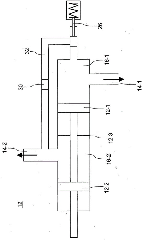
[0026] The hydraulic brake 10 includes a brake master cylinder 12, the first brake piston 12-1 of which supplies hydraulic brake pressure to the first brake circuit 14-1, and the second brake piston 12-2 of which supplies hydraulic brake pressure to the first brake circuit 14-1. A second brake circuit 14-2 separate from circuit 14-1 supplies hydraulic brake pressure.

[0027] For example from figure 1 ...


PUM


Abstract

The invention relates to a brake system (1) for a motor vehicle, comprising a hydraulic brake (10), a brake cylinder (12) of which has a first and a second brake piston (12-1, 12-2), wherein the first brake piston (12-1) supplies a first brake circuit (14-1), which is associated with a first vehicle axle, with hydraulic brake pressure and the second brake piston (12-2) supplies a second brake circuit (14-2), which is separate from the first brake circuit and is associated with a second vehicle axle, with hydraulic brake pressure, an electric motor (100) on the first vehicle axle, which electric motor can be used as a recuperator, and a blending means (26), which withdraws hydraulic fluid from the first brake circuit (14-1) during a recuperation phase of the electric motor (100). The invention is characterized in that a separating wall (12-3) is formed in the brake cylinder (12) between the first and second brake piston (12-1, 12-2), which separating wall divides the brake cylinder (12) into a first pressure chamber (16-1) associated with the first brake piston (12-1) and, separated therefrom, a second pressure chamber (16-2) associated with the second brake piston (12-2), and that the first and second brake piston (12-1, 12-2) are rigidly connected to each other.

Description

technical field [0001] The invention relates to a brake system for a motor vehicle of the type specified in the preamble of claim 1 . Background technique [0002] It is well known that there is a problem in hybrid vehicles where maximum regeneration / recovery should occur during braking with an electrically driven rear axle and where the mechanical braking device - which is connected in parallel to the electric machine - should be as small as possible brake at the same time. The reason for this is that the largest possible proportion of the braking energy should be converted into electrical energy. However, due to different actual situations, the regenerative power of the motor battery pack is not stable, but is related to various boundary conditions, such as the state of charge of the battery, the operating temperature of the motor, and so on. It is therefore desirable for the braking system to be compound-braking, ie to allow a flexible distribution of the braking power ...

Claims


Application Information

Patent Timeline
Patent Type & Authority Applications(China)
IPC IPC(8): B60T1/10B60T8/26B60T11/20B60T13/58B60T17/22
CPCB60T8/267B60T1/10B60T8/26B60T11/20B60T13/586B60T13/745B60T13/746B60T17/226B60T2270/604
Inventor T·克灵格尔W·施密德
Owner AUDI AG
Learn More