
High-temperature and high-pressure core removal device and method for alumina-based ceramic core removal
A high-temperature and high-pressure, base ceramic technology, applied in the field of high-temperature alloy castings, can solve problems such as difficulty in core removal, and achieve the effects of reducing material selection, reducing equipment costs, and saving resources
- Summary
- Abstract
- Description
- Claims
- Application Information
AI Technical Summary
Problems solved by technology
Method used
Image

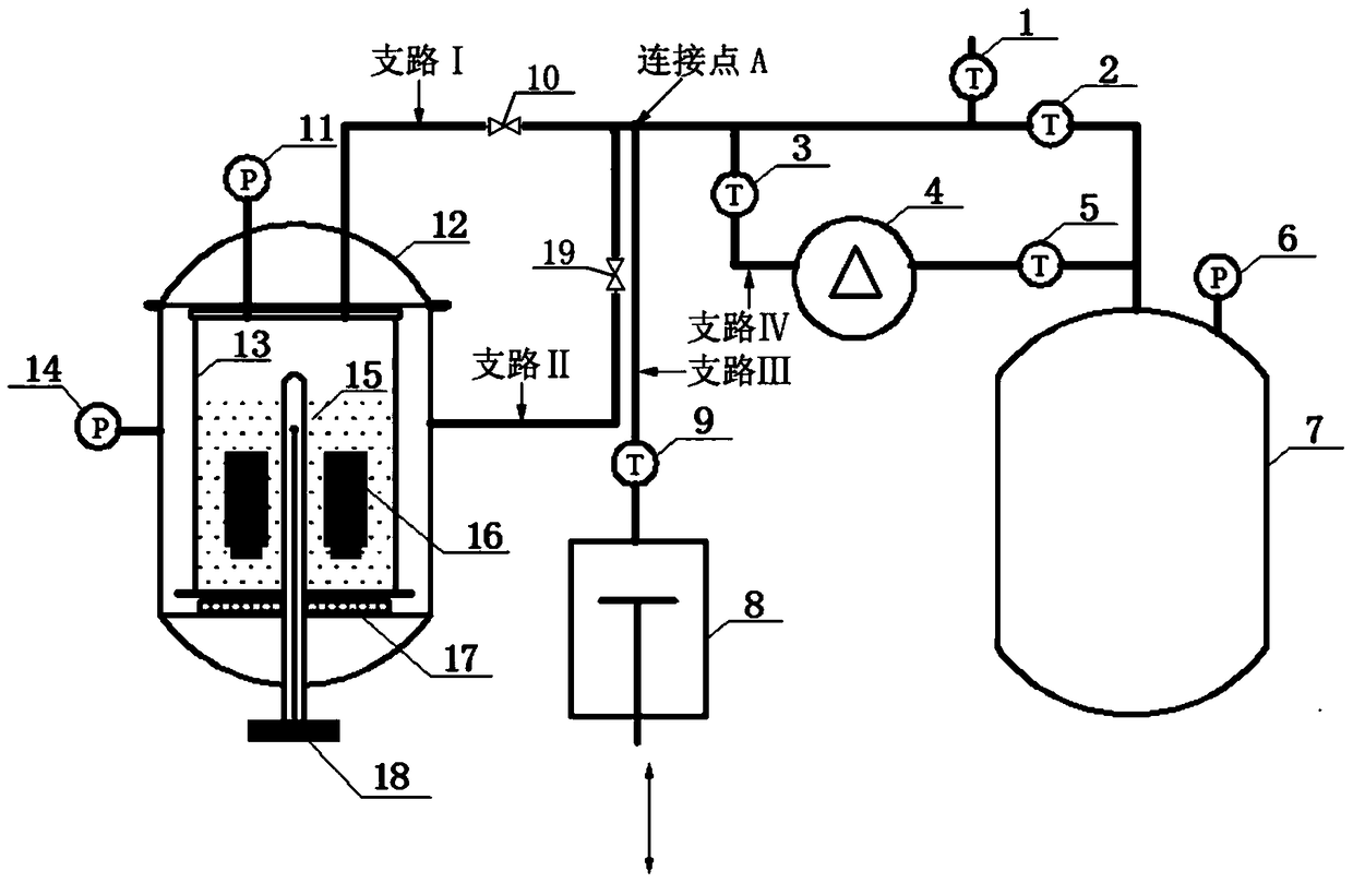
Examples
Embodiment 1
[0080] In this embodiment, the above-mentioned core removal device is used to remove the core through high temperature and alternating high pressure. The process is as follows:
[0081] Put the casting into the reaction tank 13, and add 150 kg of KOH solution with a mass concentration of 55%, and the reaction tank is installed in the pressure-resistant kettle body 12.
[0082] Open the valve A2, the nitrogen gas from the nitrogen storage tank 7 directly enters the reaction tank 13 and the pressure-resistant kettle body 12 through the gas flow regulator I10 and the gas flow regulator II19, and then reaches the nitrogen storage tank 7, the reaction tank 13 and the pressure-resistant kettle After the pressure in the body 12 is equalized, the valve A2 is closed.
[0083] Open the valve C5 and valve B3 in turn, and turn on the nitrogen compressor 4. The nitrogen flowing out of the nitrogen storage tank 7, after being pressurized by the nitrogen compressor 4, enters the reaction bar...
Embodiment 2
[0092] In this embodiment, the above-mentioned core removal device is used to remove the core through high temperature and alternating high pressure. The process is as follows:
[0093] Put the casting into the reaction tank 13, and add 175 kg of KOH solution with a mass concentration of 70%, and the reaction tank is installed in the pressure-resistant kettle body 12.
[0094] Open the valve A2, the nitrogen gas from the nitrogen storage tank 7 directly enters the reaction tank 13 and the pressure-resistant kettle body 12 through the gas flow regulator I10 and the gas flow regulator II19, and then reaches the nitrogen storage tank 7, the reaction tank 13 and the pressure-resistant kettle After the pressure in the body 12 is equalized, the valve A2 is closed.
[0095] Open the valve C5 and valve B3 in turn, and turn on the nitrogen compressor 4. The nitrogen flowing out of the nitrogen storage tank 7, after being pressurized by the nitrogen compressor 4, enters the reaction mat...
Embodiment 3
[0104] In this embodiment, the above-mentioned core removal device is used to remove the core through high temperature and constant high pressure. The process is as follows:
[0105] The casting is put into the reaction tank 13, and 180 kg of KOH solution with a mass concentration of 80% is added, and the reaction tank 13 is installed in the pressure-resistant kettle body 12.
[0106] Open the valve A2, the nitrogen gas from the nitrogen storage tank 7 directly enters the reaction tank 13 and the pressure-resistant kettle body 12 through the gas flow regulator I10 and the gas flow regulator II19, and then reaches the nitrogen storage tank 7, the reaction tank 13 and the pressure-resistant kettle After the pressure in the body 12 is equalized, the valve A2 is closed.
[0107] Open the valve C5 and valve B3 in turn, and turn on the nitrogen compressor 4. The nitrogen flowing out of the nitrogen storage tank 7, after being pressurized by the nitrogen compressor 4, enters the reac...
PUM
 Abstract
Description
Claims
Application Information