
Battery conveying device

A conveying device and battery technology, which is applied in the direction of conveyors, conveyor objects, transportation and packaging, etc., can solve the problem of battery rolling out, and achieve the effect of improving the service life

Pending Publication Date: 2017-04-26
YANCHENG CITY LONG XIANG MACHINERY MFG PLANT
View PDF0 Cites 3 Cited by
  • Summary
  • Abstract
  • Description
  • Claims
  • Application Information

AI Technical Summary

Problems solved by technology

[0002] At present, the batteries we often use are generally cylindrical or round. Due to this structure, when the battery is being transported, it is easy for the battery to roll out from both sides of the conveyor belt, and it needs to be manually picked up and put back into the conveyor belt.

Method used


Image

  • Battery conveying device
  • Battery conveying device

Examples


Embodiment Construction

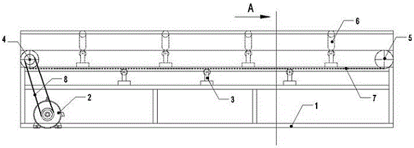
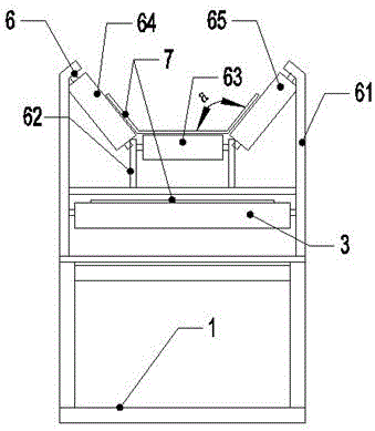
[0011] Depend on figure 1 , figure 2 It is known that a battery conveying device includes a frame 1, the frame 1 is provided with three layers, the first layer is the bottom layer with a geared motor 2 installed; the second layer is the middle layer with at least one lower roller 3 installed; The three-layer is the top floor, whose left end is equipped with a drive roller 4, and the right end is equipped with a driven roller 5, and at least one upper idler part 6 is installed in the middle; the reduction motor 2 is connected with the drive roller 4 through a transmission belt 8; the drive roller 4 and The driven roller 5 is connected by a conveyor belt 7, and the conveyor belt 7 part located below is placed on the top of the lower idler roller 3 after connection, and the conveyor belt 7 part located above is placed on the top of the upper idler roller part 6 after connection; the upper idler roller Part 6 is composed of two long brackets 61 symmetrically fixed on the top lay...


PUM


Abstract

The invention relates to a battery conveying device. The battery conveying device comprises a frame (1). The frame is characterized in that an upper supporting roller part (6) is formed by two long brackets (61) which are symmetrically fixed on the top layer of the frame (1), two short brackets (62), an upper supporting roller (63), a left supporting roller (64) and a right supporting roller (65); the two short brackets (62) are fixed on the frame (1), the upper supporting roller (63) is movably connected between the two short brackets (62), the left supporting roller (64) is movably connected between the long bracket (61) and the short bracket (62) on the left side of the upper supporting roller (63), the right supporting roller (65) is movably connected between the long bracket (61) and the short bracket (62) on the right side of the upper supporting roller (63), and the mounted left supporting roller (64), the upper supporting roller (63) and the right supporting roller (65) form a trapezoidal groove structure. According to the battery conveying device provided by the invention, two sides of a conveyor belt entering the upper supporting roller upwarp through the trapezoidal groove structure, so that a battery is well prevented from rolling out of the conveyor belt.

Description

technical field [0001] The invention relates to the field of battery production auxiliary equipment, in particular to a battery conveying device. Background technique [0002] At present, the batteries we often use are generally cylindrical or round. Due to this structure, the battery is prone to roll out from both sides of the conveyor belt when the battery is being transported, and it needs to be manually picked up and put back into the conveyor belt. Contents of the invention [0003] In view of the above deficiencies, the object of the present invention is to provide a battery conveying device, which forms a trapezoidal groove structure through the left idler, upper idler, and right idler, so that both sides of the conveyor belt entering the upper idler are upturned, which is very good It prevents the battery from rolling out of the conveyor belt. Since the conveyor belt is a flexible conveyor belt, it will cater to deformation and greatly improve the service life. ...

Claims


Application Information

Patent Timeline
Patent Type & Authority Applications(China)
IPC IPC(8): B65G15/08B65G39/12
CPCB65G15/08B65G39/12
Inventor 戴荣祥戴永俊
Owner YANCHENG CITY LONG XIANG MACHINERY MFG PLANT
Learn More