
Smoke exhausting device

The technology of a smoke exhaust device and a smoke exhaust pipe is applied in the field of smoke exhaust, which can solve the problems of low smoke exhaust efficiency and oil fume escape of the smoke exhaust device, and achieve the effects of increasing the smoking range and improving the smoke exhaust efficiency.

Active Publication Date: 2017-04-26
GUANGDONG MIDEA WHITE GOODS TECH INNOVATION CENT CO LTD +1
View PDF3 Cites 4 Cited by
  • Summary
  • Abstract
  • Description
  • Claims
  • Application Information

AI Technical Summary

Problems solved by technology

For example, the suction of the smoke exhaust device is mainly concentrated near the suction port, and the suction force for the upper edge and the lower edge of the smoke exhaust device is insufficient, so that the oil fume easily escapes from the edge of the smoke exhaust device and spreads toward the user, which makes the smoke exhaust device The smoke extraction efficiency is low, which also brings a negative experience to the user

Method used


Image

  • Smoke exhausting device
  • Smoke exhausting device
  • Smoke exhausting device

Examples


Embodiment Construction

[0031] Embodiments of the present invention are described in detail below, examples of which are shown in the drawings, wherein the same or similar reference numerals denote the same or similar elements or elements having the same or similar functions throughout. The embodiments described below by referring to the figures are exemplary only for explaining the present invention and should not be construed as limiting the present invention.

[0032] In describing the present invention, it should be understood that the terms "center", "longitudinal", "transverse", "length", "width", "thickness", "upper", "lower", "front", " Orientation indicated by rear, left, right, vertical, horizontal, top, bottom, inside, outside, clockwise, counterclockwise, etc. The positional relationship is based on the orientation or positional relationship shown in the drawings, which is only for the convenience of describing the present invention and simplifying the description, rather than indicating ...


PUM


Abstract

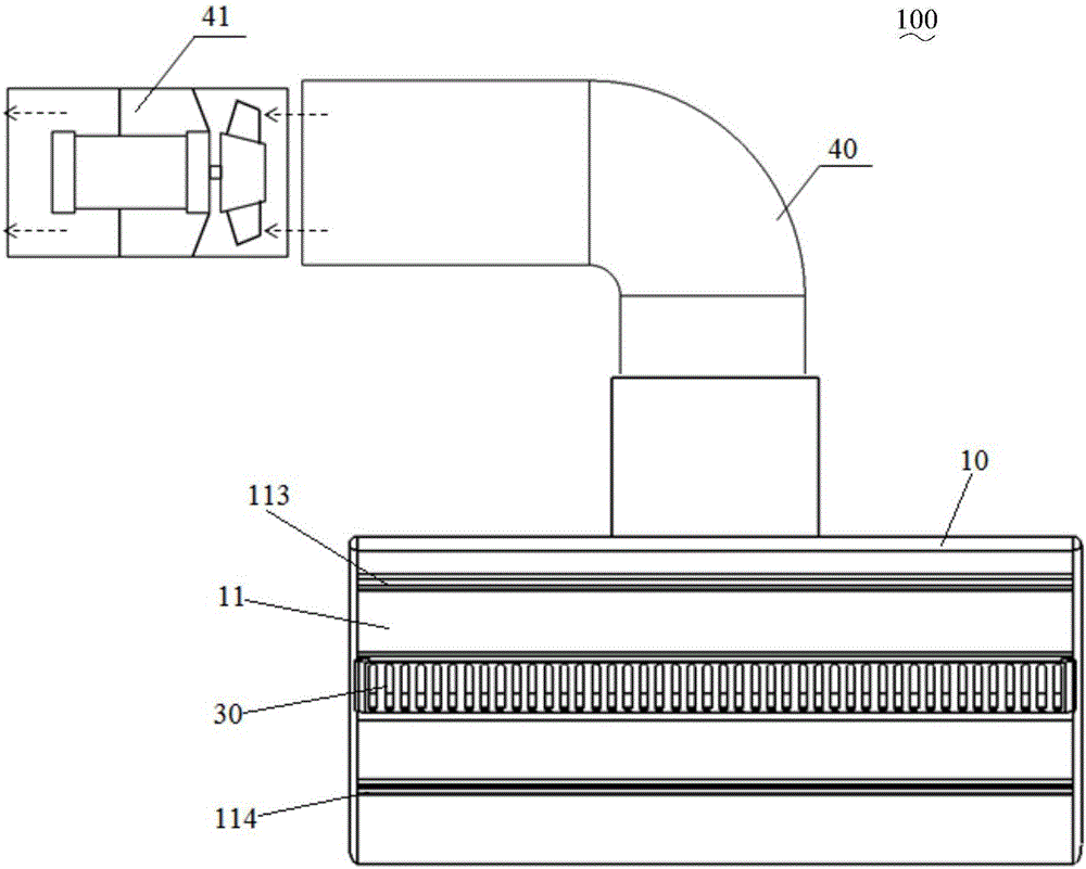
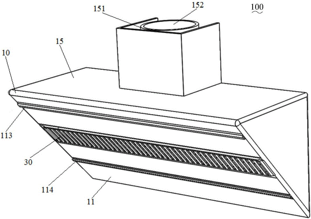
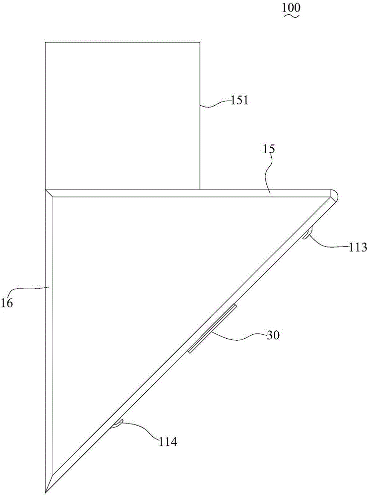
The invention discloses a smoke exhausting device. The smoke exhausting device comprises a cover body and an airflow generating device, wherein the cover body comprises a smoke absorbing surface plate; a first jet flow port, a second jet flow port and a smoke absorbing channel are arranged at intervals on the smoke absorbing surface plate; the smoke absorbing channel is positioned between the first jet flow port and the second jet pot; a smooth curved surface is formed at an inlet side edge of the smoke absorbing channel; the jet flow outgoing direction of the first jet flow port and the jet flow outgoing direction of the second jet flow port both face the curved surface; the airflow generating device is used for inputting airflow into the cover body; the first jet flow port is used for converting the airflow into first jet flow and jetting to an inlet of the smoke absorbing channel; the second jet flow port is used for converting the airflow into second jet flow and jetting to the inlet of the smoke absorbing channel; the curved surface is used for turning the first jet flow and the second jet flow into the smoke absorbing channel in order to form a negative pressure area at the inlet of the smoke absorbing channel. Therefore, the smoke absorbing range of the smoke exhausting device can be expanded, and oil smoke is hardly outwards dispersed.

Description

technical field [0001] The invention relates to the technical field of smoke exhaust, in particular to a smoke exhaust device. Background technique [0002] In the related art, the smoke exhausting efficiency of the smoke exhausting device is relatively low. For example, the suction of the smoke exhaust device is mainly concentrated near the suction port, and the suction force for the upper and lower edges of the smoke exhaust device is insufficient, so that the oily fume easily escapes from the edge of the smoke exhaust device and spreads towards the user, which makes the smoke exhaust device The smoke extraction efficiency is low, which also brings negative experience to users. Contents of the invention [0003] The present invention aims to solve at least one of the technical problems existing in the prior art. Therefore, the present invention needs to provide a smoke exhaust device. [0004] The smoke exhaust device according to the embodiment of the present inventi...

Claims


Application Information

Patent Timeline
IPC IPC(8): F24C15/20
CPCF24C15/20
Inventor 区初斌张辉
Owner GUANGDONG MIDEA WHITE GOODS TECH INNOVATION CENT CO LTD
Learn More