
Antenna module and electronic device

An electronic device and antenna module technology, which is applied to antennas, devices that enable antennas to work in different bands at the same time, antenna coupling, etc., can solve the problems of reduced assembly space, affecting antenna performance, and insufficient space for antenna device installation. Interference and radiated interference of antenna signals, effect of good antenna performance

Active Publication Date: 2017-04-26
UNIVERSAL SCIENTIFIC INDUSTRIAL (SHANGHAI) CO LTD
View PDF4 Cites 8 Cited by
  • Summary
  • Abstract
  • Description
  • Claims
  • Application Information

AI Technical Summary

Problems solved by technology

[0002] In recent years, wearable devices have been developing more and more vigorously. Not only the appearance is required to be fashionable and popular, but also the volume is required to be light and thin. The reduction of space can make the space for the antenna installation more insufficient, and further affect the performance of the antenna

Method used


Image

  • Antenna module and electronic device
  • Antenna module and electronic device
  • Antenna module and electronic device

Examples


Embodiment Construction

[0026] Various exemplary embodiments will be described more fully hereinafter with reference to the accompanying drawings, in which some exemplary embodiments are shown. However, inventive concepts may be embodied in many different forms and should not be construed as limited to the illustrative embodiments set forth herein. Rather, these exemplary embodiments are provided so that this disclosure will be thorough and complete, and will fully convey the scope of the inventive concept to those skilled in the art. In the drawings, the size and relative sizes of layers and regions may be exaggerated for clarity. Like numbers indicate like components throughout.

[0027] It will be understood that although the terms first, second, third etc. may be used herein to describe various components, these components should not be limited by these terms. These terms are used to distinguish one component from another. Thus, a first component discussed below could be termed a second compon...


PUM


Abstract

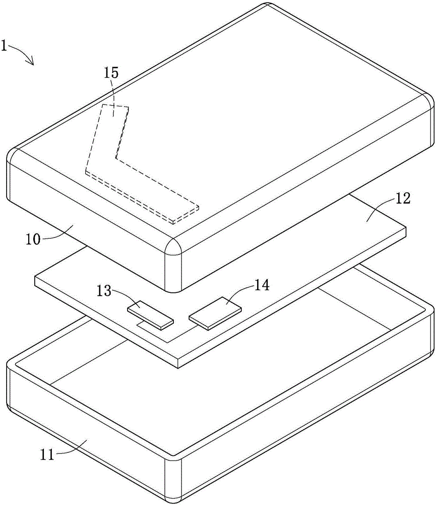
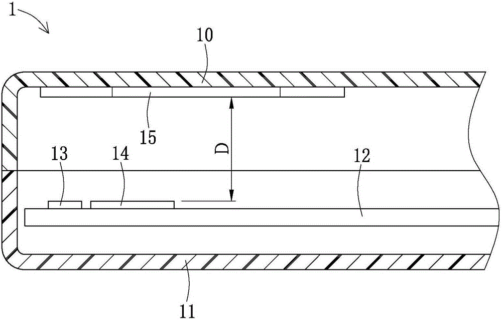
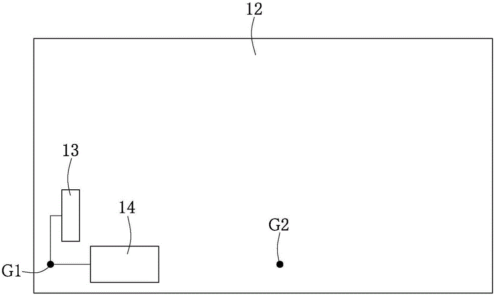
The invention discloses an antenna module and electronic device. The electronic device includes a shell, a circuit board, a first antenna, a second antenna and a third antenna. The circuit board is arranged in the shell. The first antenna provides a first frequency and is arranged on the circuit board. The second antenna provides a second frequency, is arranged on the circuit board and is adjacent to the first antenna. The third antenna includes a first antenna structure and a second antenna structure. The first antenna structure provides a third frequency, the second antenna structure provides a fourth frequency, and the third antenna is arranged on an inner side of the shell and is away from the first antenna and the second antenna at predetermined distance. The first antenna and the second antenna are jointly electrically connected to a first grounding area. The third antenna is electrically connected to a second grounding area. The antenna module utilizes the arrangement that at least two antennas are not connected to the same grounding area and antennas with similar frequency are particularly staggered in space arrangement, and thus can effectively reduce interference among the plurality of antennas.

Description

technical field [0001] The present invention relates to an antenna module, in particular to an antenna module with multiple antennas. The invention also relates to an electronic device with the antenna module. Background technique [0002] In recent years, wearable devices have been developing more and more vigorously. Not only the appearance is required to be fashionable and popular, but also the volume is required to be light and thin. The reduction of the space can make the space for the antenna device more insufficient, and further affect the performance of the antenna. [0003] When multiple antennas are installed in the same space, the mutual interference and influence will be more serious. Therefore, how to provide an antenna module suitable for installing multiple antennas in a small space has become an important issue in the industry. Contents of the invention [0004] The main purpose of the present invention is to provide an electronic device suitable for arra...

Claims


Application Information

Patent Timeline
Patent Type & Authority Applications(China)
IPC IPC(8): H01Q1/52H01Q1/50H01Q5/307
CPCH01Q1/50H01Q1/521H01Q5/307
Inventor 邱弘伟
Owner UNIVERSAL SCIENTIFIC INDUSTRIAL (SHANGHAI) CO LTD
Learn More