
Bearing bush and pedal device with said bearing bush

A technology of bearing bushing and tilting plate, applied in the directions of bearings, bearing components, shafts and bearings, etc., can solve the problem of decreased operating feeling of automobiles, and achieve the effect of improving operating feeling, preventing descending, and preventing the generation of abnormal noise.

Inactive Publication Date: 2017-04-26
OILES CORP
View PDF13 Cites 1 Cited by
  • Summary
  • Abstract
  • Description
  • Claims
  • Application Information

AI Technical Summary

Problems solved by technology

In either case, there is a problem of deteriorating the handling feel of the car

Method used


Image

  • Bearing bush and pedal device with said bearing bush
  • Bearing bush and pedal device with said bearing bush
  • Bearing bush and pedal device with said bearing bush

Examples


Embodiment Construction

[0044] Next, a more detailed description of the present invention and modes of carrying out the present invention will be provided with reference to preferred embodiments shown in the accompanying drawings. It should be noted that the present invention is not limited to these Examples.

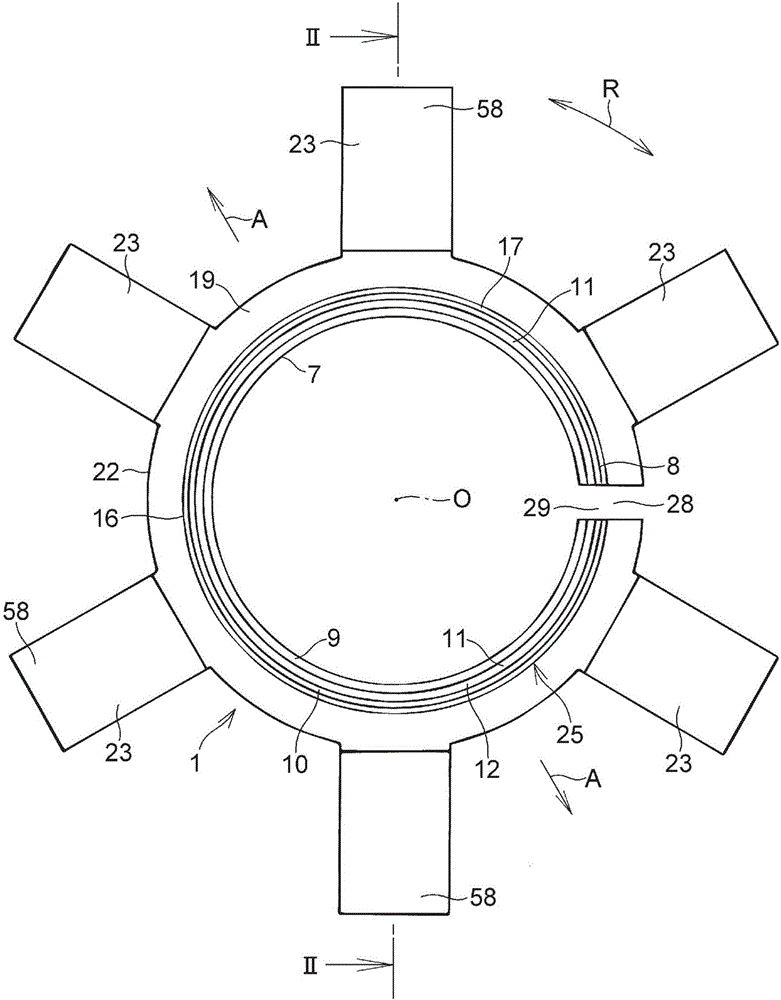
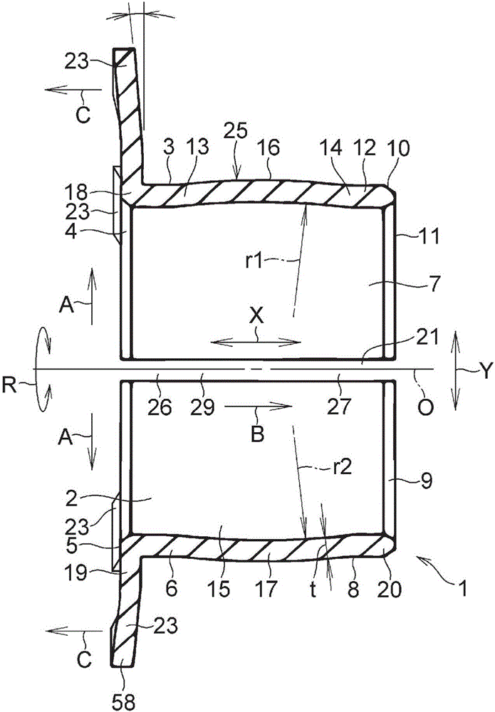
[0045] exist figure 1 and figure 2 Among them, the bearing bush 1 according to the present embodiment is composed of the following parts: a cylindrical part 6 having a cylindrical inner surface 2, a cylindrical outer surface 3, an annular tapered ring continuously connected to the cylindrical inner surface 2 constriction inner surface 4, and an annular annular end surface 5 continuously connected to the annular annular constriction inner surface 4 in the axial direction X; a cylindrical portion 12 having a cylindrical inner surface 7, a cylindrical outer surface 8. The annular annular tapered inner surface 9 and the annular annular tapered outer surface 10 continuously connected to the cyli...


PUM


Abstract

A bearing bush 1 comprises a circular cylindrical section 6 having a circular cylindrical inner surface 2 and a circular cylindrical outer surface 3; a circular cylindrical section 12 having a circular cylindrical inner surface 7 and a circular cylindrical outer surface 8; a bulge 17 provided between the circular cylindrical sections 6, 12 in the axial direction X and having a concave inner surface 15 and a convex outer surface 16; an annular flange 19 extended toward the outside A in the radial direction Y at the other end 18 of the circular cylindrical section 6 in the axial direction X; a slit 21 for dividing the circular cylindrical sections 6, 12, the bulge 17, and the annular flange 19; and a plurality of tilted plate sections 23 formed integrally with the outer peripheral edge 22 of the annular flange 19 and extended in a tilted position toward the outside A in the radial direction Y from the outer peripheral edge 22.

Description

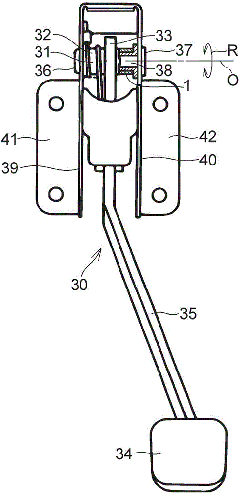
technical field [0001] The present invention relates to a bearing bush and a pedal device having the bearing bush. Background technique [0002] In general, a brake pedal or a clutch pedal of an automobile is rotatably supported by a shaft member supported by a pedal bracket fixed to a body member (eg, an instrument panel) through a cylindrical boss. [0003] In the case of a conventional pedal device having a pivotally supported structure between a pedal bracket and a shaft member, a pair of synthetic resin-made bearing bushes each having a ring portion at their respective ends are press-fitted into A boss with a pedal arm fixed to its outer peripheral surface so that the rear surface of the ring portion abuts against the end face of the boss, and a shaft member made of a bolt is inserted into a bearing bush with a predetermined gap therebetween (bearing clearance ), the shaft member is fastened by nuts and fixed between a pair of pedal brackets. [0004] prior art litera...

Claims


Application Information

Patent Timeline
Patent Type & Authority Applications(China)
IPC IPC(8): F16C25/04F16C17/10F16C33/12F16C33/14F16C33/20G05G1/44
CPCF16C11/045F16C17/10F16C25/04F16C27/02F16C33/12F16C33/128F16C33/20F16C33/203F16C33/206F16C2204/10F16C2204/20F16C2204/72F16C2208/60F16C2370/00G05G1/44G05G23/00F16C33/125
Inventor 熊泽胜利沖村明彦
Owner OILES CORP
Learn More