
Protection device for edges of fusible tinplate

A protection device and tin plate technology, applied in the field of electroplating, can solve the problems of bright edge of strip steel, affecting the surface quality of strip steel, affecting the quality of strip steel electroplating finished products, etc., to prevent bright edge or white edge, ensure electroplating quality and The effect of welding performance

Inactive Publication Date: 2017-05-10
福建中日达金属有限公司 +1
View PDF7 Cites 0 Cited by
  • Summary
  • Abstract
  • Description
  • Claims
  • Application Information

AI Technical Summary

Problems solved by technology

However, due to the uneven distribution of current during the electroplating process, the current on both sides of the strip in the width direction will be relatively concentrated, resulting in a relatively high amount of tin plating on the edge of the strip, and the thickness of the tin layer is too high
This will lead to bright or white edges on the electroplated steel strip, which will greatly affect the surface quality of the strip steel, and at the same time will reduce the welding performance of the strip steel and affect the quality of the electroplated steel strip.

Method used


Image

  • Protection device for edges of fusible tinplate
  • Protection device for edges of fusible tinplate
  • Protection device for edges of fusible tinplate

Examples


Embodiment Construction

[0028] In order to make the object, technical solution and advantages of the present invention clearer, the present invention will be further described in detail below in conjunction with the accompanying drawings and specific implementation methods. It should be understood that the specific embodiments described here are only used to explain the present invention, and do not limit the protection scope of the present invention.

[0029] It should be noted that when an element is referred to as being “fixed on”, “disposed on” or “installed on” another element, it may be directly on the other element or there may be an intervening element. When an element is considered to be "connected" to another element, it may be directly connected to the other element or there may be an intervening element at the same time; the specific way that one element is fixedly connected to another element can be realized through existing technologies, and will not be discussed here. To repeat it agai...


PUM


Abstract

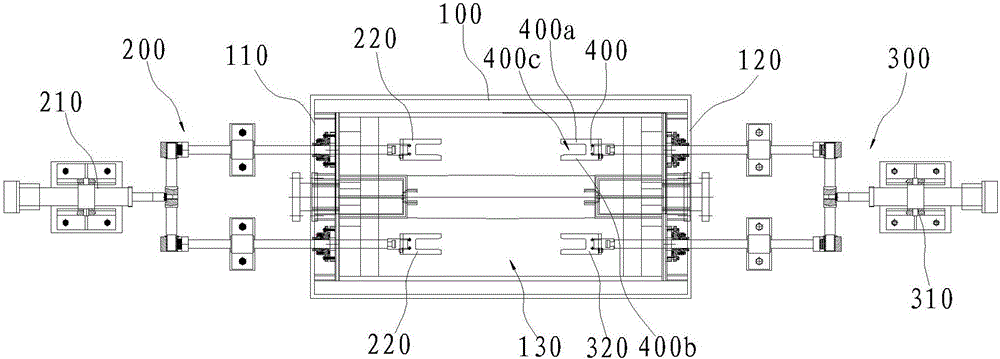
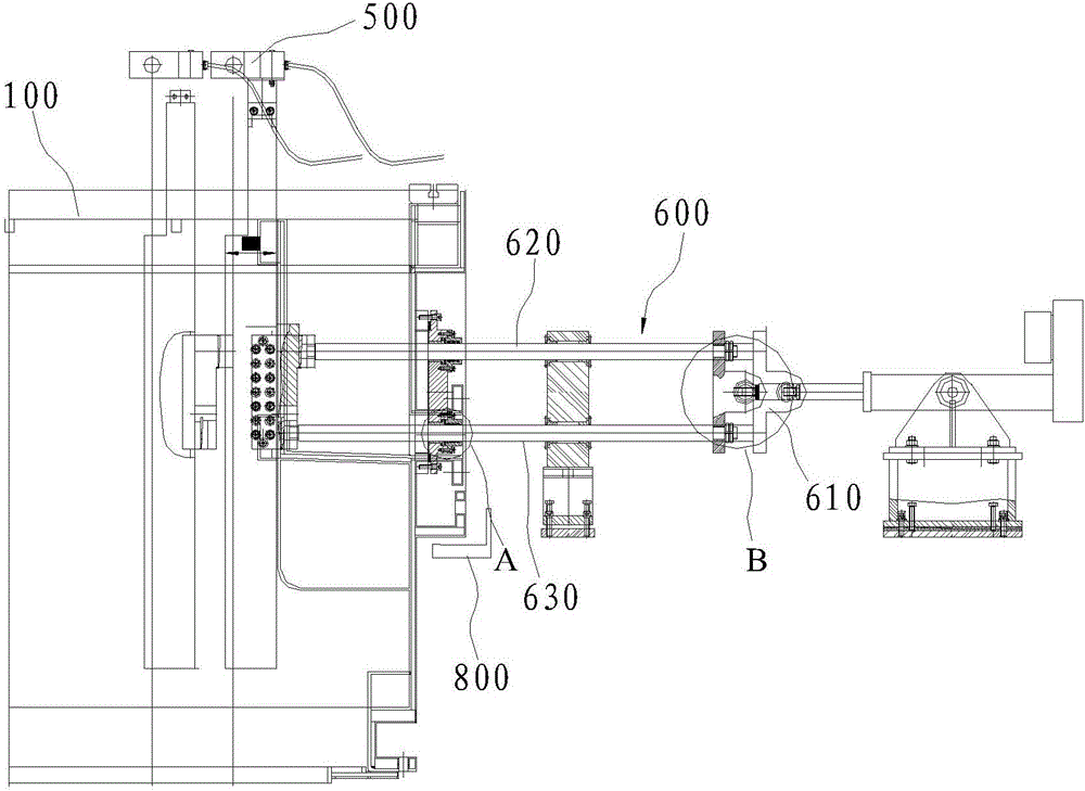
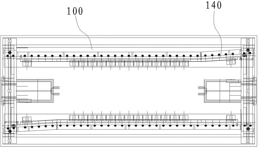
The invention discloses a protection device for the edges of a fusible tinplate. The protection device comprises a control unit; at least one plating bath, which comprises a first bath end and a second bath end and provided with a plating bath cavity; a first protector, which comprises a first driving part electrically connected with the control unit and a first protective cover covering a plate edge at one side of the tinplate so as to reduce the edge effect of current, wherein the first protective cover is arranged on the plating bath cavity and located on the first bath end; and a second protector, which comprises a second driving part electrically connected with the control unit and a second protective cover covering a plate edge at the other side of the tinplate so as to reduce the edge effect of current, wherein the second protective cover is arranged on the plating bath cavity and located on the second bath end. Thus, electroplating current on the edges of the tinplate can be effectively blocked, so the phenomenon of bright edges or white edges caused by great plate thickness due to excess concentration of current at the plate edges is prevented; and thus, the electroplating quality and welding performance of a product are guaranteed.

Description

technical field [0001] The invention relates to the technical field of electroplating, in particular to a fusible tinplate edge protection device. Background technique [0002] Traditionally, in order to make the strip steel have excellent characteristics in terms of corrosion resistance and heat resistance to be suitable for production and use in the fields of beverage, medicine, chemical industry, etc., it is usually necessary to electroplate the strip steel. The commonly used electroplating method is tin plating deal with. The steel strip gradually enters the electroplating tank through the guiding function of the guide roller, and ion exchange occurs with the soluble tin anode under the participation of the electroplating solution to plate a thin layer of tin on the surface of the steel plate. However, due to the uneven distribution of current during the electroplating process, the current on both sides of the strip in the width direction will be relatively concentrated...

Claims


Application Information

Patent Timeline
IPC IPC(8): C25D7/06C25D3/30
CPCC25D7/0614C25D3/30C25D7/0692
Inventor 连永朱友桂林联桓许文祥李寻省
Owner 福建中日达金属有限公司
Learn More