Electronic control intelligent lock equipment

An electronic control and intelligent lock technology, applied in the application of electric check locks, building locks, locks, etc., can solve the problems of lack of intelligent control, complicated elderly and children, and inhumane design, so as to ensure intelligent reduce the number of keys to carry, and ensure the effect of convenience and intelligence

Inactive Publication Date: 2017-05-10
徐海恩
View PDF9 Cites 1 Cited by
  • Summary
  • Abstract
  • Description
  • Claims
  • Application Information

AI Technical Summary

Problems solved by technology

[0002] With the continuous improvement of people's life safety awareness, many people are increasingly pursuing the performance and quality of door locks, so smart devices are more and more popular with people. The design of smart lock devices is different from that of general door lock devices. There is a big difference, so it is more humanized and intelligent when used. The general door lock equipment is equipped with a mechanical key to achieve the purpose of unlocking, but this unlocking method is too single and not intelligent enough. To a certain extent, it cannot Avoid some accidents, so the safety performance is not high, and the general door lock equipment is not suitable for the elderly and children to a certain extent. Due to the cumbersome design of the mechanical device, the unlocking process is too complicated for the elderly and children. , lack of intelligent control, not humanized enough in design

Method used


Image

  • Electronic control intelligent lock equipment
  • Electronic control intelligent lock equipment
  • Electronic control intelligent lock equipment

Examples


Embodiment Construction

[0020] The specific embodiments of the present invention will be further described below in conjunction with the accompanying drawings. It should be noted here that the descriptions of these embodiments are used to help understand the present invention, but are not intended to limit the present invention. In addition, the technical features involved in the various embodiments of the present invention described below may be combined with each other as long as they do not constitute a conflict with each other.

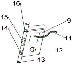
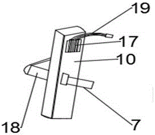
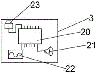
[0021] see Figure 1 to Figure 4 , the present invention provides a technical solution: an electronically controlled intelligent lock device, including a front panel 1, including a slide cover 2, an intelligent unlocking device 3, a password keyboard 4, a front handle 5, a lock hole 6, Rotate square steel 7, wire interface 8, lock body 9, rear panel 10, slide cover 2 is installed on the upper side of front panel 1, has small roller at the junction of slide cover and fro...


PUM


Abstract

The invention discloses electronic control intelligent lock equipment which comprises a front panel. A sliding cover is mounted on the upper side of the front panel. An intelligent unlocking device is mounted in the sliding cover. A code keyboard is mounted under the sliding cover. A front handle is mounted below the code keyboard. A lock hole is formed below the front handle. An electric wire port is mounted on the upper left side of the front panel. A lock body is mounted on the left side of the front panel. A rear panel is mounted on the left side of the lock body. A lock body power wire is mounted on the upper side of the lock body. Rotating square steel is mounted below the left portion of the front panel. According to the electronic control intelligent lock equipment, due to the arranged intelligent unlocking device, a user can carry out multiple electronic control unlocking manners, and intelligentization of the intelligent lock equipment is guaranteed; the code keyboard is arranged, and therefore under the condition that a sudden failure happens to a display device, the intelligent lock equipment can work normally, and the performance of the intelligent lock equipment is guaranteed; and a power source is arranged, and therefore the display device can achieve standby work for a long time, and the work performance of the intelligent lock equipment is guaranteed.

Description

technical field [0001] The invention relates to the technical field of intelligent lock equipment, in particular to an electronically controlled intelligent lock equipment. Background technique [0002] With the continuous improvement of people's life safety awareness, many people are increasingly pursuing the performance and quality of door locks, so smart devices are more and more popular with people. The design of smart lock devices is different from that of general door lock devices. There is a big difference, so it is more humanized and intelligent when used. The general door lock equipment is equipped with a mechanical key to achieve the purpose of unlocking, but this unlocking method is too single and not intelligent enough. To a certain extent, it cannot To avoid some unexpected situations, so the safety performance is not high, and the general door lock equipment is not suitable for the elderly and children to a certain extent. Due to the cumbersome design of the me...

Claims


Application Information

Patent Timeline
Patent Type & Authority Applications(China)
IPC IPC(8): E05B3/00E05B63/14E05B49/00E05B17/22G07C9/00
CPCE05B3/00E05B17/22E05B17/226E05B49/00E05B63/146G07C9/00563
Inventor 徐海恩
Owner 徐海恩
Why Eureka
Try Eureka