
Street lamp equipment

A technology of equipment and street lamps, applied in the field of electric power, can solve the problem of single function of street lamps

Inactive Publication Date: 2017-05-10
STATE GRID BEIJING ELECTRIC POWER +1
View PDF6 Cites 4 Cited by
  • Summary
  • Abstract
  • Description
  • Claims
  • Application Information

AI Technical Summary

Problems solved by technology

[0004] The main purpose of the present invention is to provide a street light device to solve the problem that the street lights in the prior art have relatively single functions

Method used


Image

  • Street lamp equipment
  • Street lamp equipment
  • Street lamp equipment

Examples


Embodiment Construction

[0029] It should be noted that, in the case of no conflict, the embodiments in the present application and the features in the embodiments can be combined with each other. The present invention will be described in detail below with reference to the accompanying drawings and examples.

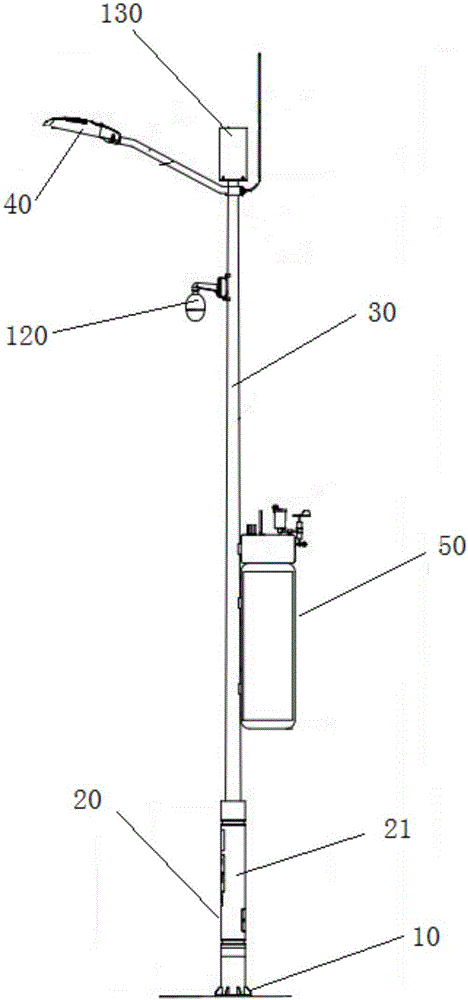
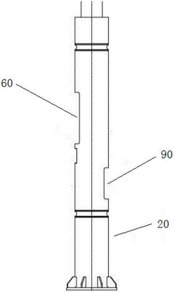
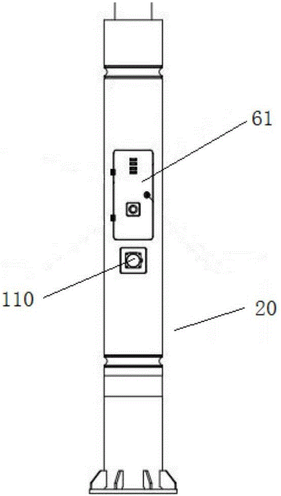
[0030] The present invention provides a street light equipment, please refer to Figure 1 to Figure 8 , including a base 10, a light pole 30 and a light 40 installed on the light pole 30, the street light equipment also includes: a charging pile 20, the charging pile 20 is arranged on the base 10, and external equipment is charged through the charging pile 20; the charging pile 20 is disposed between the base 10 and the light pole 30 , and the light pole 30 is connected to the base 10 through the charging pile 20 .

[0031] The street light equipment in the present invention realizes the design of integrating lighting and charging by setting the charging pile 20 and the light pole 30 on the ba...


PUM


Abstract

The invention provides street lamp equipment. The street lamp equipment comprises a base, a lamp rod, and an illumination lamp mounted on the lamp rod. The street lamp equipment further comprises a charge pile; the charge pile is arranged on the base; external equipment is charged through the charge pile; the charge pile is arranged between the base and the lamp rod; and the lamp rod is connected with the base through the charge pile. The street lamp equipment solves the problem of single function of a street lamp in the prior art.

Description

technical field [0001] The present invention relates to the field of electric power, in particular to a street light device. Background technique [0002] Smart city is a new concept and new model that uses new-generation information technologies such as the Internet of Things, cloud computing, big data, and spatial geographic information integration to promote smart urban planning, construction, management, and services. Smart cities need to integrate various technologies in terms of "traffic management, environmental monitoring, public safety, emergency management, energy conservation and emission reduction, and social security", and realize "convenient public services and refined urban management" on the basis of intelligent infrastructure. and livable living environment”. [0003] At present, in cities, especially in the design of street lamps, street lamps are only used as lighting equipment, and the characteristics of building street lamps into smart street lamps in u...

Claims


Application Information

Patent Timeline
IPC IPC(8): F21S8/08F21V33/00F21V23/00F21V23/04F21W131/103
CPCF21S8/086F21V23/003F21V23/04F21V33/00F21V33/0052F21W2131/103
Inventor 白鹭陈春光乔生繁刘雪松宋云龙陈壬贤于德海刘嘉于乐淘贾忱然李静樊星覃炜瞳李铁姜玉稀章干卿培
Owner STATE GRID BEIJING ELECTRIC POWER
Learn More