
Energy-efficiency outdoor power distribution cabinet installation and locking device

A technology for locking devices and power distribution cabinets, which is applied in substation/power distribution device shells, electrical components, substation/switch layout details, etc., which can solve the inconvenience of installation and replacement of outdoor power distribution cabinets, low efficiency of installation and disassembly, and damage to concrete floors and other problems, to achieve the effect of high disassembly and installation efficiency, long service life and stable operation

Active Publication Date: 2017-05-10
东营中达石油设备有限公司
View PDF5 Cites 0 Cited by
  • Summary
  • Abstract
  • Description
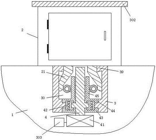
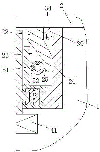
  • Claims
  • Application Information

AI Technical Summary

Problems solved by technology

[0002] The outdoor power distribution cabinet is a container for storing electrical control devices, which is widely used in industry and life. The installation of the existing outdoor power distribution cabinet is generally fixed on the concrete floor by bolts, screws and other fasteners. , and the use of bolts, screws and other fasteners requires multiple installation holes on the concrete floor, which will cause damage to the concrete floor, and the use of bolts and screws to fix the connection is prone to loosening during long-term use And other defects, but also need to process the matching thread structure, so it is easy to cause damage to the structure and shorten the life. It is troublesome, and it is extremely inconvenient to install and replace the outdoor power distribution cabinet, and the efficiency of installation and disassembly is low

Method used


Image

  • Energy-efficiency outdoor power distribution cabinet installation and locking device
  • Energy-efficiency outdoor power distribution cabinet installation and locking device

Examples


Embodiment Construction

[0008] Combine below Figure 1-2 The present invention will be described in detail.

[0009] An energy-saving outdoor power distribution cabinet installation and locking device according to an embodiment of the present invention is used to fix the outdoor power distribution cabinet 2 on the cement pier 1, and the cement pier 1 is installed with a solid body with a hollow cavity 30 inside. Connector 3, the bottom surface of the outdoor power distribution cabinet 2 is integrally provided with two deformable connecting arms 21 symmetrically distributed on the left and right, and the two deformable connecting arms 21 are used to be inserted into the fixed In the hollow cavity 30 of the connector 3, the deformable connecting arm 21 includes a fixed part 22 connected with the outdoor power distribution cabinet 2, a deformable part 23 connected with the fixed part 22 and a The guide part 24 connected with the deformable part 23, wherein, the outer surface of the guide part 24 is a p...


PUM


Abstract

The invention provides an energy-efficiency outdoor power distribution cabinet installation and locking device which is used for fixing an outdoor power distribution cabinet (2) on a cement column (1). The cement column (1) is internally provided with a firm connection device (3) which is internally provided with a hollow cavity (30). The bottom surface of the outdoor power distribution cabinet (2) is provided with two deformable connection arms (21) in an integrated manner, and the two deformable connection arms (21) are distributed in a horizontally symmetric manner. The two deformable connection arms (21) are used for being inserted in the hollow cavity (30) of the firm connection device (3) through elastic deformation. Each deformable connection arm (21) comprises a fixing part (22) connected with the outdoor power distribution cabinet (2), a deformable part (23) connected with the fixing part (22), and a guiding part (24) connected with the deformable part (23).

Description

technical field [0001] The invention relates to the field of outdoor power distribution cabinet installation, in particular to an energy-saving outdoor power distribution cabinet installation locking device. Background technique [0002] The outdoor power distribution cabinet is a container for storing electrical control devices, which is widely used in industry and life. The installation of the existing outdoor power distribution cabinet is generally fixed on the concrete floor by bolts, screws and other fasteners. , and the use of bolts, screws and other fasteners requires multiple installation holes on the concrete floor, which will cause damage to the concrete floor, and the use of bolts and screws to fix the connection is prone to loosening during long-term use And other defects, but also need to process the matching thread structure, so it is easy to cause damage to the structure and shorten the life. It is troublesome, and it is extremely inconvenient to install and ...

Claims


Application Information

Patent Timeline
Patent Type & Authority Applications(China)
IPC IPC(8): H02B1/30
CPCH02B1/303
Inventor 何先进
Owner 东营中达石油设备有限公司
Learn More