Adjustable sliding-rail type suspension girder operating platform for high-rise building

A technology for operating platforms and high-rise buildings, applied in the directions of buildings, building structures, housing structures, etc., which can solve the problems of leaning, poor comfort, and poor safety of the operating platform, and improve safety, which is not easy. The effect of shaking and reducing fatigue

Active Publication Date: 2017-05-17
CHINA CONSTR STEEL STRUCTURE CORP LTD
View PDF6 Cites 6 Cited by
  • Summary
  • Abstract
  • Description
  • Claims
  • Application Information

AI Technical Summary

Problems solved by technology

[0006] The main purpose of the present invention is to propose a high-rise building adjustable slide-rail type suspension beam operating platform that is adaptable, convenient to transfer, safe and comfortable, aiming at solving the problem that the operating platform in the prior art cannot be applied to a variety of suspension beams and requires other personnel Assist in the technical issues of station transfer, poor operating platform safety and poor comfort

Method used


Image

  • Adjustable sliding-rail type suspension girder operating platform for high-rise building
  • Adjustable sliding-rail type suspension girder operating platform for high-rise building
  • Adjustable sliding-rail type suspension girder operating platform for high-rise building

Examples


Embodiment 1

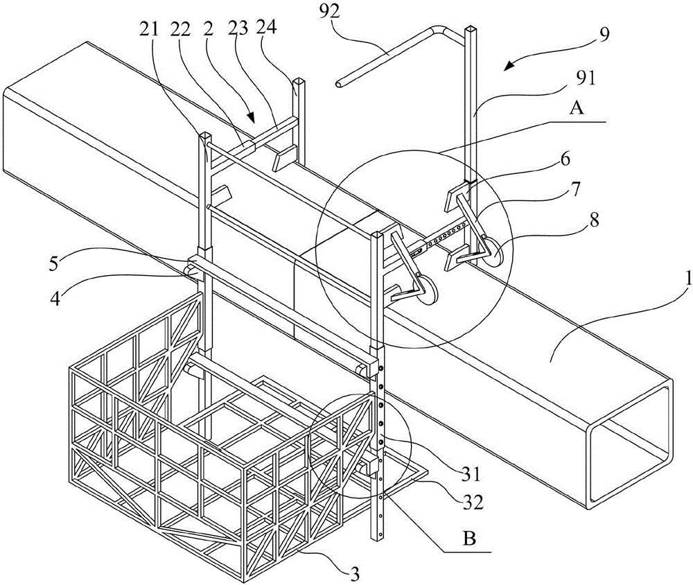
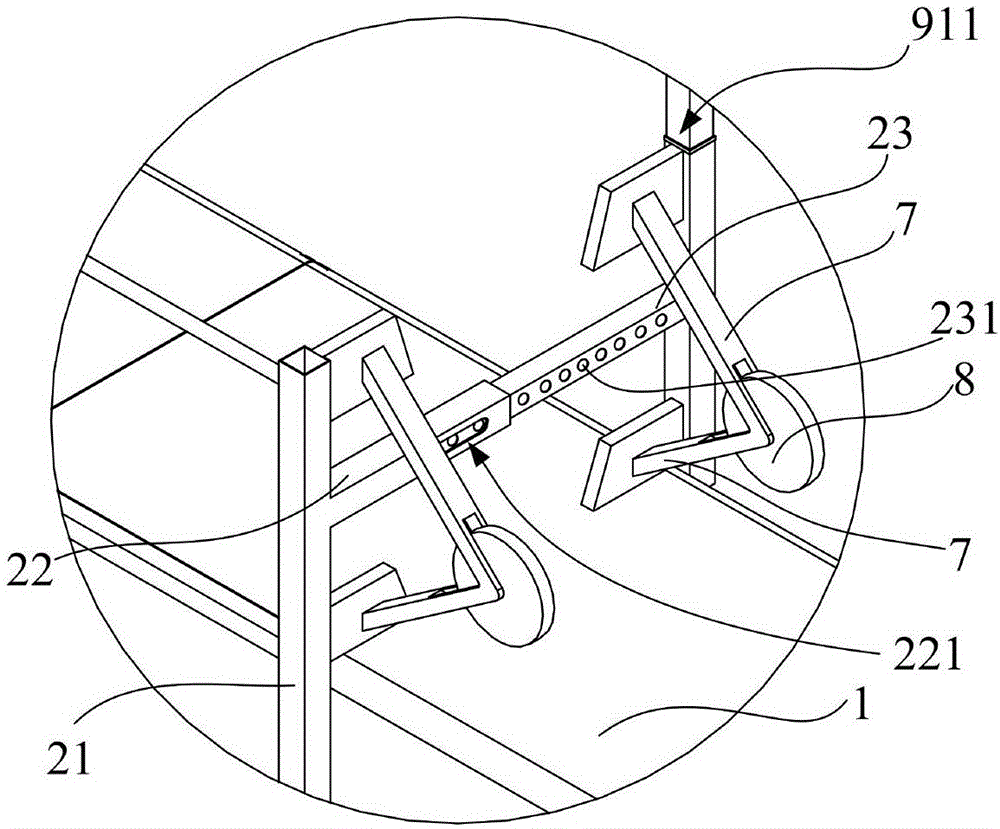
[0034] See Figure 1 to Figure 4 , the present invention proposes an adjustable slide rail type suspension beam operating platform for high-rise buildings, the operating platform includes a basket frame body 3 and a hook structure arranged on the left and right sides of the basket frame body 3 facing the suspension beam and can hang the operation platform on the suspension beam 1 2. The hook structure 2 includes a telescopic crossbeam that can be stretched and adjusted in length, and a front clamping arm 21 and a rear clamping arm 24 that are vertically and fixedly connected to the telescopic crossbeam. Among them, the telescopic crossbeam of this embodiment is a segmented structure, including a front crossbeam 22 and a rear crossbeam 23 that are connected to each other. The front crossbeam 22 and the rear crossbeam 23 are partially nested with each other and the telescopic crossbeam can be adjusted by the telescopic device. at the working length of the cantilever beam 1. The...

Embodiment 2

[0044] This embodiment is the same as Embodiment 1 except for the following features: In this embodiment, the telescopic device used to adjust the working length of the telescopic beam hanging on the suspension beam includes a positioning bump that is arranged in the rear cross beam and can protrude elastically. The bottom of the block is also provided with a spring, and the front beam surface is provided with some positioning through holes to cooperate with the positioning projections to adjust the working length of the telescopic beam.

[0045] In this embodiment, in order to hang the operating platform on the suspension beam, it is necessary to first obtain the cross-sectional width of the suspension beam by means of measurement, etc., and then press the positioning protrusion to make it downward without interfering with the positioning through hole. When the positioning protrusion When the block will not interfere with the positioning through hole, move the front beam away ...

Embodiment 3

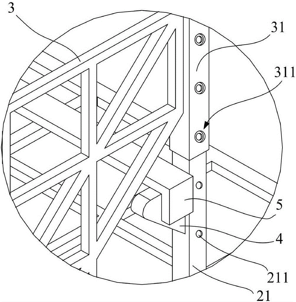
[0048] This embodiment is the same as Embodiment 1 except for the following features: the height adjustment device for adjusting the height of the basket frame includes a projection that is arranged inside the front clamping arm and can elastically protrude from the surface, and the bottom edge of the basket sliding sleeve is provided with The groove and the protrusion are positioned in cooperation.

[0049] In this embodiment, when the basket frame needs to be slid vertically, first press the protrusion to make it downward without interfering with the movement of the basket sliding sleeve, and then slide the basket sliding sleeve along the front clamping arm Move in the vertical direction, and when the operating platform is translated in place in the vertical direction, the protrusion will interfere with the groove provided on the bottom edge of the basket sliding sleeve, thereby determining the working height of the operating platform.

[0050] Compared with the operating pl...


PUM


Abstract

The invention discloses an adjustable sliding-rail type suspension girder operating platform for a high-rise building. The operating platform comprises a basketry body and a hanger structure. The hanger structure comprises a telescopic beam, front clamping arms and rear clamping arms, wherein the front clamping arms and the rear clamping arms are all perpendicularly and fixedly connected with the telescopic beam. The telescopic beam comprises a front beam body and a rear beam body which are partially and mutually sleeved, and the front beam body and the rear beam body can adjust the working length of the telescopic beam through a telescopic device. The side, close to the front clamping arms, of the basketry body is provided with basketry sliding sleeves, the basketry sliding sleeves are connected with the front clamping arms in a sleeving mode, and the height of the basketry body can be adjusted through a height adjusting device. According to the adjustable sliding-rail type suspension girder operating platform for the high-rise building, the relative planar distances of the front clamping arms and the rear clamping arms can be adjusted through the front beam body and the rear beam body so that the working length of the telescopic beam can be adaptable to the width of the cross section of a suspension girder, and a hanger of the operating platform can be adaptable to the suspension girders with different specifications and sizes. In addition, adjustment of the working height of the basketry body is achieved through the height adjusting device between the front clamping arms and the basketry sliding sleeves, and thus the requirement that the operating platform is adaptable to fastening of the suspension girders under different working conditions is met.

Description

technical field [0001] The invention relates to the field of high-rise building installation engineering tooling equipment, in particular to an adjustable slide rail type suspension beam operating platform for high-rise buildings. Background technique [0002] With the continuous development of my country's economy, the number of high-rise buildings continues to increase, and most high-rise buildings use steel structures as the main structure, and the nodes of steel structures are generally welded or bolted. Since the steel structure project is under construction, the floor slab can only be laid after the suspension beam is installed. Therefore, the steel structure suspension beam is generally temporarily fixed after being hoisted in place, and then the operator needs to use the corresponding equipment to fasten the suspension beam. The operation is extremely dangerous, and creates greater psychological pressure on the construction workers. [0003] In the prior art, when t...

Claims


Application Information

Patent Timeline
Patent Type & Authority Applications(China)
IPC IPC(8): E04G3/28E04G5/04
CPCE04G3/28E04G5/045E04G2003/283
Inventor 黄敏俞霆张芳旭林明辉潘文彬高微
Owner CHINA CONSTR STEEL STRUCTURE CORP LTD
Why Eureka
Try Eureka