Use an industrial endoscope to observe the structure of the internal condition of the valve

An endoscope and industrial technology, which is applied in the field of channel structures reserved for observing the internal conditions of valves with industrial endoscopes, can solve the problems of reducing work efficiency, wasting media, and missing work and time, so as to achieve timely observation and save time. and human and material resources

Active Publication Date: 2019-01-01
天津澳特斯阀门制造有限公司
View PDF6 Cites 0 Cited by
  • Summary
  • Abstract
  • Description
  • Claims
  • Application Information

AI Technical Summary

Problems solved by technology

[0002] At present, valves have been widely used. However, because the valve is a sealed device for conveying pressure fluid medium, the current valve does not have a visual channel to observe the internal situation of the valve. Therefore, the internal situation of the existing valve includes the working process of the opening and closing parts. It is impossible to observe directly in real time. If you need to observe and understand the internal situation of the valve, you need to disassemble the valve from the pipeline, or enter the pipeline and the inside of the valve through the maintenance manhole set on the pipeline when the medium is stopped and the medium in the pipeline is drained. Observation, this kind of observation method not only delays work and time, but also wastes medium and reduces work efficiency. It can be seen that the existing valves can no longer meet the needs of timely grasping the internal situation of the valve and making the continuous, safe and stable operation of the medium conveying pipeline
[0003] Through searching, no patent publications related to this patent application have been found

Method used


Image

  • Use an industrial endoscope to observe the structure of the internal condition of the valve
  • Use an industrial endoscope to observe the structure of the internal condition of the valve
  • Use an industrial endoscope to observe the structure of the internal condition of the valve

Examples


Embodiment Construction

[0021] In order to further understand the content, characteristics and effects of the present invention, the following examples are given, and detailed descriptions are given below with reference to the accompanying drawings. It should be noted that this embodiment is descriptive, not restrictive, and cannot thereby limit the protection scope of the present invention.

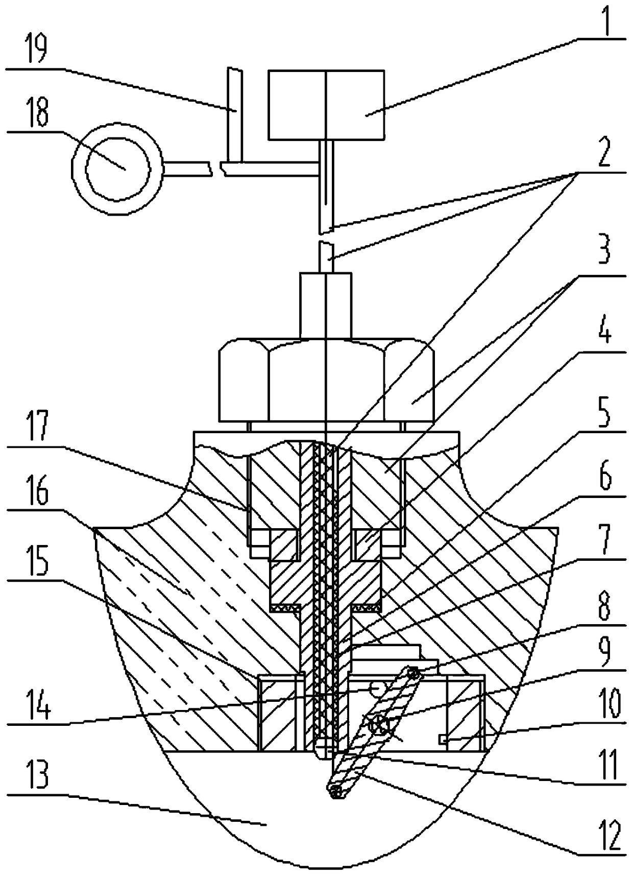
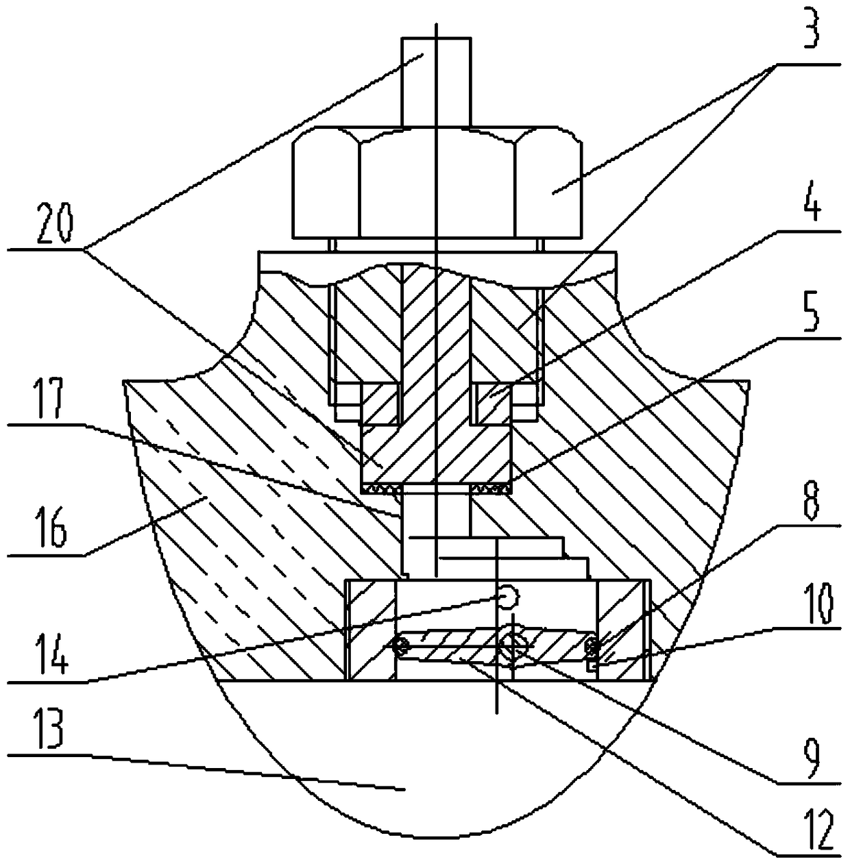
[0022] A channel structure reserved for using an industrial endoscope to observe the internal conditions of the valve, such as figure 1 As shown, the structure includes a through hole 17 made in the valve body 16, an industrial endoscope tip 11 with the functions of light emitting, photographing and data transmission, a conductive light guide 2, a resin sleeve 7, a catheter 6, and is arranged on the valve body. The working eyepiece part 1 outside the body, the shooting transmission part 18 set outside the valve body, the remote data line 19 set outside the valve body and the eccentric butterfly check valve 15, ...


PUM


Abstract

The invention relates to a channel structure with an industrial endoscope reserved and used for observing the internal condition of a valve. The channel structure comprises a through pore channel formed in a valve body, an industrial endoscope distal end part with the light-emitting, photographing and data transmission functions, conductive light transmitting bundles, a resin sleeve, a guide pipe, a working eyepiece part arranged outside the valve body, a shooting transmission part arranged outside the valve body, a remote data line arranged outside the valve body and an eccentric-type butterfly swing check valve. According to the channel structure, the internal condition of the valve can be directly observed or photographed manually on the site regularly or whenever and wherever possible, and data information can be remotely transmitted; there is no need to remove and dismantle the valve from an installation pipeline, the phenomenon that conveying of pipeline media is broken is avoided, time, manpower and material resources are saved, and observation work is made more timely, convenient and fast; and real-time monitoring can be conducted, a reliable visual means is provided for determining the working state of the valve, the data information about the observed internal condition of the valve can further be stored, remote transmission and remote diagnosis are carried out, and therefore the problem of the valve can be better solved correctly.

Description

technical field [0001] The invention belongs to the technical field of valve equipment, in particular to a channel structure reserved for using an industrial endoscope to observe the internal conditions of a valve. Background technique [0002] At present, valves have been widely used. However, because the valve is a sealed device for conveying pressure fluid medium, the current valve does not have a visual channel to observe the internal situation of the valve. Therefore, the internal situation of the existing valve includes the working process of the opening and closing parts. It is impossible to observe directly in real time. If you need to observe and understand the internal situation of the valve, you need to disassemble the valve from the pipeline, or enter the pipeline and the inside of the valve through the maintenance manhole set on the pipeline when the medium is stopped and the medium in the pipeline is drained. Observation, this observation method not only delays...

Claims


Application Information

Patent Timeline
Patent Type & Authority Patents(China)
IPC IPC(8): F16K37/00
CPCF16K37/0058
Inventor 张二南裴叶青段淑清张国栋庞慧高国伟兴冯之春李成敬新蕊
Owner 天津澳特斯阀门制造有限公司
Why Eureka
Try Eureka