Cable splicing method using communication cable splicing auxiliary jig

A communication cable and auxiliary fixture technology, which is applied in the direction of connecting/terminating cable equipment, etc., can solve the problems of loose line sequence fixation, disordered communication cable sequence, complicated line sequence matching work, etc., and achieve simple cable connection process, The effect of increasing speed and speeding up

Inactive Publication Date: 2018-03-02
HARBIN UNIV OF SCI & TECH +1
View PDF8 Cites 0 Cited by
  • Summary
  • Abstract
  • Description
  • Claims
  • Application Information

AI Technical Summary

Problems solved by technology

[0005] The present invention aims to solve the problem that the line sequence pairing work is complicated in the existing cable connection work, and the sequence of the communication cables is likely to be disordered due to the loose line sequence fixing in the connection work. The present invention provides a communication cable connection auxiliary fixture for The cable connection method

Method used


Image

  • Cable splicing method using communication cable splicing auxiliary jig
  • Cable splicing method using communication cable splicing auxiliary jig
  • Cable splicing method using communication cable splicing auxiliary jig

Examples


specific Embodiment approach 1

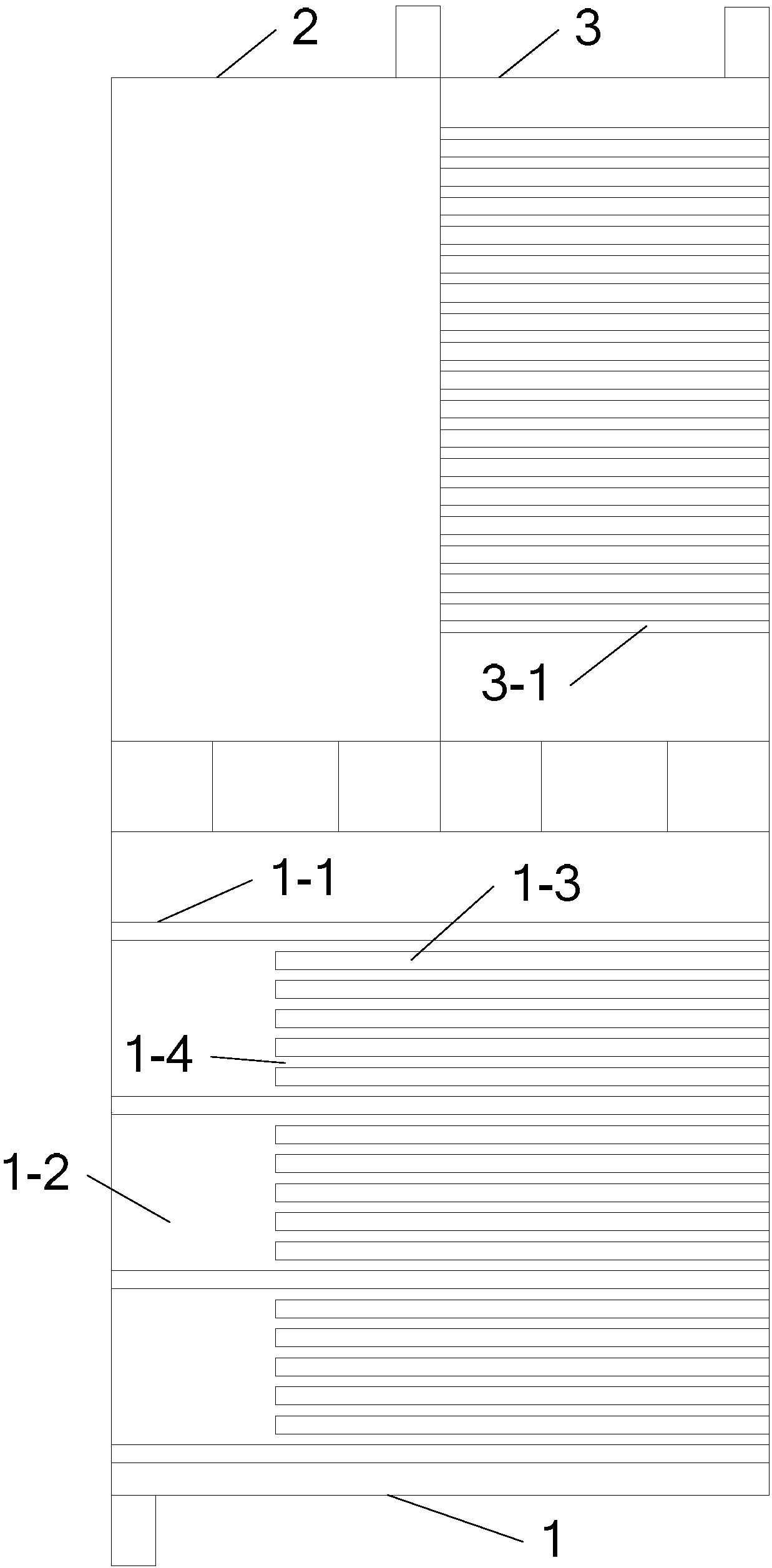
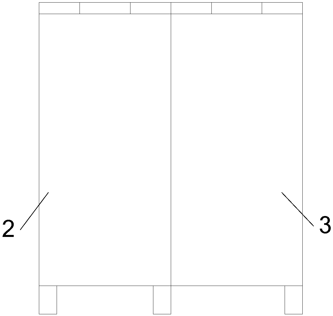
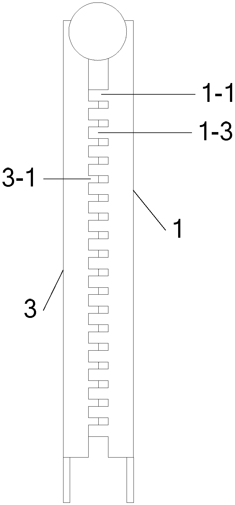
[0028] Specific implementation mode one: see Figure 1 to Figure 5 Describe this embodiment, the cable splicing method described in this embodiment using the communication cable splicing auxiliary jig, the communication cable splicing auxiliary jig includes a lower splint 1, a first upper splint 2 and a second upper splint 3, the first The upper splint 2 and the second upper splint 3 are arranged side by side, and are respectively connected to the rotation shaft of the lower splint 1. The lower splint 1 is equally divided into N clamping areas 1-2 by the partition plate 1-1 in its length direction, and each clamping plate There are a plurality of lower splint teeth 1-3 evenly distributed in the area 1-2, and a line is formed between two adjacent lower splint teeth 1-3 and between the lower splint teeth 1-3 on both sides and the partition plate 1-1. Slot 1-4, N is an integer greater than or equal to 3,

[0029] The lower splint tooth 1-3 is parallel to the partition 1-1, and t...

specific Embodiment approach 2

[0036] Specific implementation mode two: see Figure 1 to Figure 5 Describe this embodiment. The difference between this embodiment and the cable splicing method using the communication cable splicing auxiliary fixture described in Embodiment 1 or 2 is that the cross section of the lower splint teeth 1-3 is rectangular or the upper part is circular. arc, the lower part is a rectangular bulge.

[0037] In this embodiment, the upper part is a circular arc, the lower part is a rectangular protrusion, and the upper surface is smooth, which is convenient for combing the inner core of the cable.

specific Embodiment approach 3

[0038] Specific implementation mode three: see Figure 1 to Figure 8 This embodiment is described. The difference between this embodiment and the cable splicing method using the communication cable connection auxiliary fixture described in the first embodiment is that the communication cable connection auxiliary fixture also includes a telescopic link 4, and the two telescopic links 4 Both ends are provided with columnar protrusions,

[0039] The lower surface of the lower splint 1 is provided with a groove 1-5, and the columnar protrusion at one end of the telescopic link 4 is used to be embedded in the groove 1-5 on the lower splint 1 .

[0040] In this embodiment, the telescopic connecting rod 4 is arranged between two sets of communication cable connection auxiliary fixtures, and is fixed on the two lower splints 1, and the two sets of communication cable connection auxiliary fixtures are relatively fixed, so that each communication cable connection auxiliary fixture The ...


PUM


Abstract

A cable splicing method executed by means of a communication cable splicing auxiliary clamp belongs to the field of communication cable splicing. The method settles a defect of communication cable disorder caused by complicated wire sequence pairing operation and low wire fixation firmness in existing cable splicing operation. The method comprises the steps of 1, parallelly placing two communication cable splicing auxiliary clamps in a manner that a second clamping board of each communication cable splicing auxiliary clamp is arranged at inside, processing sheaths of two communication cables so that the inner wire cores of the two communication cables are placed into the wire ducts of the two communication cable splicing auxiliary clamps according to a wire sequence, closing the first upper clamping boards of the two clamps, adjusting the lengths of the two communication cables, and then closing second upper clamping boards of the two clamps so that the two communication cables are fixedly clamped between the corresponding wire ducts and upper clamping board teeth; and 2, pairing the inner wire cores of the two communication cables according to the wire sequence, and performing one-by-one splicing through a clamp according to the wire sequence, thereby finishing communication cable splicing. The cable splicing method is mainly used for splicing the cable.

Description

technical field [0001] The invention belongs to the field of communication cable connection. Background technique [0002] With the rapid development of communication technology, there are many application occasions for communication cables, but because communication cables are mostly used for short-distance large-scale channel signal transmission, there are more wire pairs. Taking voice signal communication cables as an example, there are often 50 internal cables Right above. Therefore, there is a large workload when the communication cables are wired to each branch box or line board. [0003] The laying and operating environment of communication optical cables is complex, and its working conditions are harsh, especially in the case of laying in multi-line and complex urban environments. In actual work, situations such as biting by small animals, digging during construction, and scraping by super-high vehicles often occur. Sometimes it also involves adding communication ...

Claims


Application Information

Patent Timeline
Patent Type & Authority Patents(China)
IPC IPC(8): H02G1/14
CPCH02G1/14
Inventor 刘欢张爽
Owner HARBIN UNIV OF SCI & TECH
Why Eureka
Try Eureka