Method for Splicing Optical Fiber by Using Optical Cable Splicing Fixture

A technology of optical cable and fixture, which is applied in the field of optical cable fusion, can solve the problems of complex work of optical fiber pairing and fixing optical fiber, low efficiency of fusion splicing, etc., and achieve the effect of speeding up, increasing speed, and simple fiber fusion process

Active Publication Date: 2019-06-14
国网黑龙江省电力有限公司佳木斯供电公司 +2
View PDF5 Cites 0 Cited by
  • Summary
  • Abstract
  • Description
  • Claims
  • Application Information

AI Technical Summary

Problems solved by technology

[0005] The present invention aims to solve the problem of low fusion efficiency due to the complex work of pairing and fixing optical fibers in the existing optical cable fusion splicing process. The present invention provides a method for splicing optical fibers by using a splicing fixture

Method used


Image

  • Method for Splicing Optical Fiber by Using Optical Cable Splicing Fixture
  • Method for Splicing Optical Fiber by Using Optical Cable Splicing Fixture
  • Method for Splicing Optical Fiber by Using Optical Cable Splicing Fixture

Examples


specific Embodiment approach 1

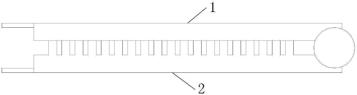
[0028] Specific implementation mode one: see Figure 1 to Figure 6 Describe this embodiment, the method for fiber splicing using an optical cable splicing fixture described in this embodiment, the described optical cable splicing fixture includes an upper cover plate 1 and a lower cover plate 2 connected by a rotating shaft,

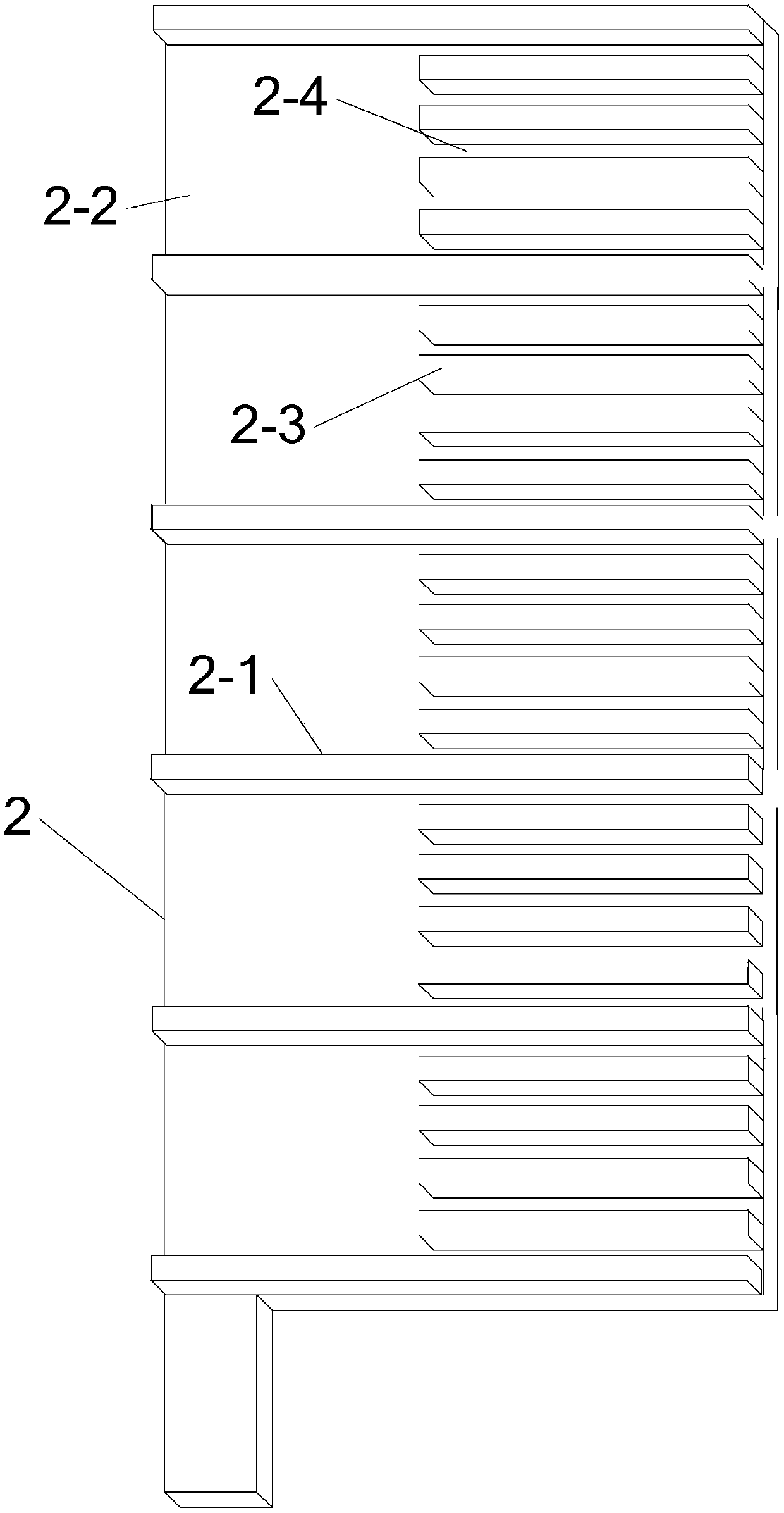
[0029] The lower cover plate 2 is evenly divided into N clamping areas 2-2 by the partition plate 2-1 in its length direction, and a plurality of splint teeth 2-3 are evenly distributed in each clamping area 2-2. A line groove 2-4 is formed between the splint teeth 2-3 and between the splint teeth 2-3 on both sides and the partition plate 2-1, N is an integer greater than or equal to 3,

[0030] The splint tooth 2-3 is parallel to the partition 2-1, and the length of the splint tooth 2-3 is less than the length of the partition 2-1;

[0031] The method comprises the steps of:

[0032] Step 1: Process the sheaths of the two optical cables to be fused, s...

specific Embodiment approach 2

[0036] Specific implementation mode two: see Figure 1 to Figure 6 This embodiment is described. The difference between this embodiment and the method of fiber splicing using the fiber splicing clamp described in the first embodiment is that one end of the splint tooth 2-3 is flush with the end of the partition plate 2-1 .

specific Embodiment approach 3

[0037] Specific implementation mode three: see Figure 1 to Figure 6 Describe this embodiment, the difference between this embodiment and the method of using the optical cable fusion clamp for optical fiber fusion described in the first or second specific embodiment is that the cross section of the splint tooth 2-3 is rectangular or the upper part is an arc , the lower part is a rectangular protrusion.

[0038] In this embodiment, the upper part is a circular arc, the lower part is a rectangular protrusion, and the upper surface is smooth, which is convenient for combing the inner core of the optical cable.


PUM


Abstract

The present invention provides a method for optical cable fiber welding by employing optical cable fiber welding clamps, belonging to the optical cable welding field. The problem is solved that the fiber pairing work and the fiber fixing work are complex in the optical cable welding to cause the low welding efficiency. The method comprises the following steps: the step 1: performing processing of the sheaths of two optical cables to be welded to allow the optical fiber cores of the two optical cables to be welded to be respectively arranged in the wire ducts of the two optical cable fiber welding clamps according to the wire sequence, cover the upper cover plates of the two optical cable fiber welding clamps and respectively lock the optical cable fiber welding clamps; and the step 2: allowing the optical fiber cores of the two optical cables to be welded to perform pairing according to the wire sequence, disposing a fiber welding machine between the two optical cable fiber welding clamps to perform fiber welding one by one according to the wire sequence so as to complete the fiber welding of the optical cables. The method for optical cable fiber melting by employing optical cable fiber welding clamps is mainly configured for the welding of the optical fiber.

Description

technical field [0001] The invention belongs to the field of optical cable welding. Background technique [0002] With the rapid development of communication technology, there are more and more applications for communication optical cables. Since the length of each optical cable is basically less than 2.5km, it is necessary to use optical cable splice boxes in long-distance communication systems to ensure the connection strength of optical cables. and reliability of data transmission. In order to ensure the connection strength, a steel wire is used to reinforce the connection between a section of optical cable, and then each fused optical fiber is arranged in layers. Optical cables have one input and one output, and there are many one input and multiple outputs. When optical cables with more than 16 cores enter the room and are distributed to different devices, an optical distribution box needs to be installed, and optical terminal boxes are often used for optical cables w...

Claims


Application Information

Patent Timeline
Patent Type & Authority Patents(China)
IPC IPC(8): G02B6/255
CPCG02B6/2553
Inventor 解忠武姜鹏李宁元王鲁昕尚方李军
Owner 国网黑龙江省电力有限公司佳木斯供电公司
Why Eureka
Try Eureka