Microscope having two access openings for the fluorescence device

A fluorescent device and microscope technology, applied in the field of microscopes, can solve problems that do not conform to ergonomics

Active Publication Date: 2017-05-17
LEICA MICROSYSTEMS CMS GMBH
View PDF7 Cites 1 Cited by
  • Summary
  • Abstract
  • Description
  • Claims
  • Application Information

AI Technical Summary

Problems solved by technology

[0008] The disadvantage here is that, on the one hand, the fluorescent device can thus only be accessed from one side, depending on which side the opening is arranged, which is not ergonomic for right-handed and / or left-handed
On the other hand, it is disadvantageous that additional, externally arranged functional components are often provided on the side of the microscope

Method used


Image

  • Microscope having two access openings for the fluorescence device
  • Microscope having two access openings for the fluorescence device
  • Microscope having two access openings for the fluorescence device

Examples


Embodiment Construction

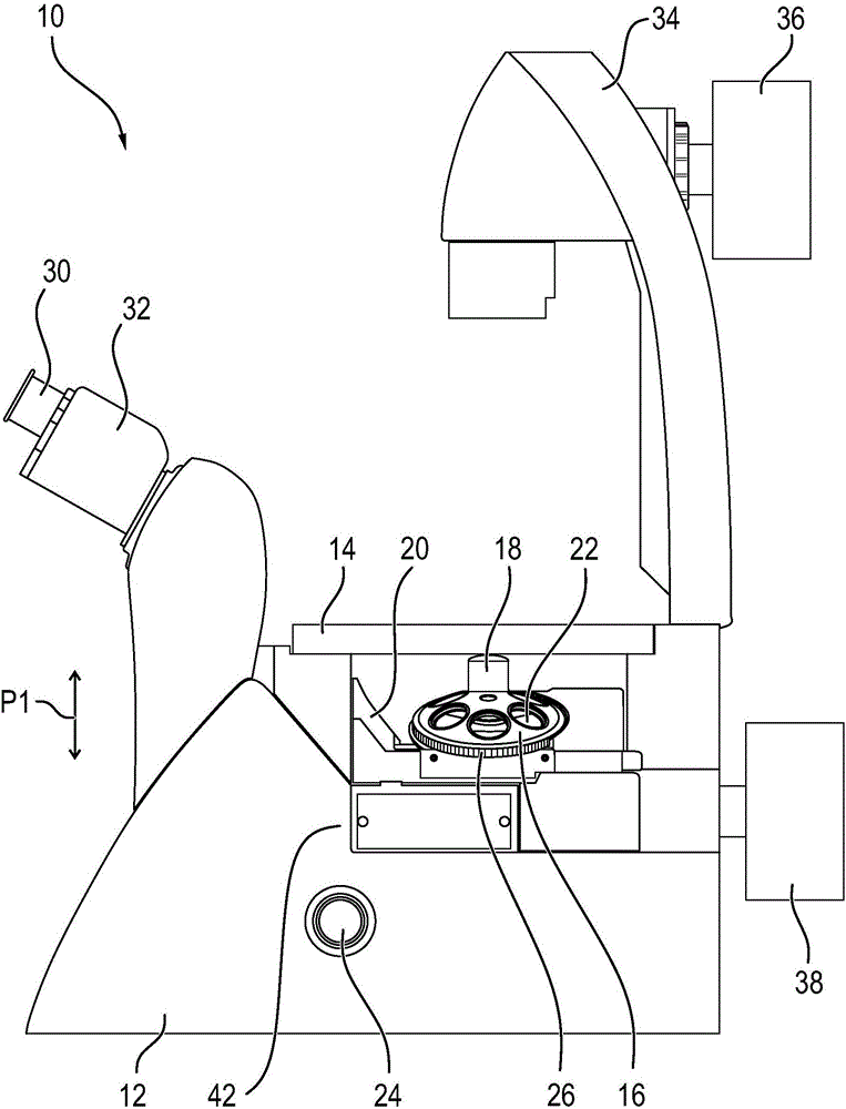
[0053] figure 1 The fluorescence microscope 10 is schematically shown in view towards the first side. The microscope 10 comprises a stand base 12 , to which is rigidly fastened an object stage 14 , on which an object to be observed, in particular in the form of a slide, can be placed.

[0054] Furthermore, an objective swivel 16 is provided, which has a plurality of recesses, one of which is marked with the reference numeral 22 for example. Objective lenses 18 can be respectively accommodated in these grooves 22, wherein, for the sake of clarity, in figure 1 Only one objective lens 18 is shown in . The objective swivel 16 is here rotatably fastened on a swivel holder 20 , so that one of the objectives 18 can be selectively swiveled along the optical axis of the microscope 10 . The objective swivel 16 is fastened obliquely to the swivel carrier 20 , so that the axis of rotation about which the objective swivel 16 can rotate extends obliquely with respect to the optical axis....


PUM


Abstract

The invention relates to a microscope (10, 100), which comprises a housing (42) and a fluorescence device (50), wherein the fluorescence device (50) is arranged in a space surrounded by the housing (42). The housing (42) has at least two openings (70, 74), by means of which the fluorescence device (50) can be accessed.

Description

technical field [0001] The invention relates to a microscope comprising a housing and a fluorescent device, wherein the fluorescent device is arranged in a space surrounded by the housing. The housing has a first opening through which the fluorescent device is accessible. Background technique [0002] In fluorescence microscopy, a fluorescent dye is excited with light of a certain wavelength, wherein the fluorescent dye then emits light of another wavelength, so-called fluorescence. Depending on the fluorochrome, the sample must be excited with different wavelengths of light. Also, depending on the dye, the wavelength of fluorescence emitted varies. [0003] In order to be able to microscopically correspond to the sample with different fluorescent dyes, the fluorescence microscope has a fluorescence unit in which several fluorescent cubes (Fluoreszenzwürfel) can be accommodated, each of which can be selectively embedded in the microscope in the light path. These fluoresc...

Claims


Application Information

Patent Timeline
IPC IPC(8): G02B21/24G02B21/00
CPCG02B21/0088G02B21/24G02B21/248G02B21/16G02B21/0076G02B21/06G02B21/18G02B21/26
Inventor 马丁·顾贝克
Owner LEICA MICROSYSTEMS CMS GMBH
Why Eureka
Try Eureka