Engagement driving type milling blade driving device

A driving device and driving technology, which is applied in feeding devices, metal processing equipment, metal processing machinery parts, etc., can solve the problems of inconvenient installation of milling blades, inconvenient manipulation of milling blades, inconvenient rotation control, etc.

Inactive Publication Date: 2017-05-24
佘峰
View PDF8 Cites 1 Cited by
  • Summary
  • Abstract
  • Description
  • Claims
  • Application Information

AI Technical Summary

Problems solved by technology

The existing milling blades are inconvenient to install and realize rotation control, and it is inconvenient to control the milling blades

Method used


Image

  • Engagement driving type milling blade driving device
  • Engagement driving type milling blade driving device
  • Engagement driving type milling blade driving device

Examples


Embodiment Construction

[0016] The preferred embodiments of the present invention will be described in detail below in conjunction with the accompanying drawings, so that the advantages and features of the present invention can be more easily understood by those skilled in the art, so as to define the protection scope of the present invention more clearly.

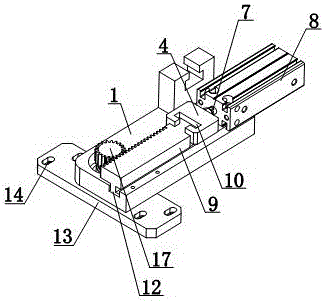
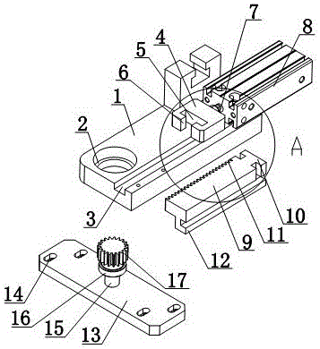
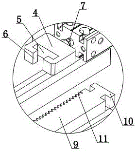
[0017] Such as Figure 1 to Figure 4 As shown, an engagement-driven milling blade driving device includes a base plate 1, a limit groove 2 is provided on the base plate 1, a guide groove 3 is provided on the base plate 1, a moving seat 4 is provided on the base plate 1, and the front of the moving seat 4 There is a card slot 5 at the bottom, and a buckle block 6 is arranged on the front of the moving seat 4, and the buckle block 6 is arranged on the front part of the card slot 5; the bottom plate 1 is provided with a drive motor 8, and the front part of the drive motor 8 is provided with a telescopic shaft 7. The telescopic shaft 7 is connected t...


PUM


Abstract

The invention discloses an engagement driving type milling blade driving device. The engagement driving type milling blade driving device comprises a bottom plate which is provided with a limiting groove; a guiding groove is formed in the bottom plate; a movable base is arranged on the bottom plate; a clamping groove is formed in the front portion of the movable base; a buckling block is arranged on the front portion of the movable base, and is arranged on the front portion of the clamping groove; a driving motor is arranged on the bottom plate; a telescopic shaft is arranged on the front portion of the driving motor, and is connected with the movable base; a movable rack is arranged on the front portion of the movable base; a clamping block is arranged on the end portion of the movable rack, and is connected into the clamping groove in a clamped manner, and the clamping block is buckled by the buckling block; a tooth groove is formed in the position of the outer side wall of the movable rack; a positioning slider is arranged at the bottom of the movable rack, and is arranged in the guiding groove; and a rotating mechanism is arranged below the bottom plate. The movable rack of the engagement driving type milling blade driving device can control a gear to rotate back and forth, the gear can perform rotating control over a rotating plate through a rotating shaft, and therefore rotating control can be conveniently performed on a milling blade.

Description

technical field [0001] The invention relates to a milling cutter device, in particular to an engagement-driven milling blade driving device. Background technique [0002] The milling blade is the saw blade, which is a saw blade composed of a large amount of carbon, tungsten, molybdenum, chromium, vanadium, cobalt or other materials, and has high thermal hardness after heat treatment. The existing milling blades are inconvenient to install and realize rotation control, and it is inconvenient to control the milling blades. Contents of the invention [0003] The present invention mainly solves the technical problems existing in the prior art, thereby providing a mobile rack that can make the movement stability better; the mobile rack can control the gear to rotate back and forth, and the gear can control the rotation of the rotating plate through the rotating shaft. , so as to facilitate the rotation control of the milling blade meshing driven milling blade driving device. ...

Claims


Application Information

Patent Timeline
Patent Type & Authority Applications(China)
IPC IPC(8): B23Q5/48
CPCB23Q5/48
Inventor 佘峰
Owner 佘峰
Why Eureka
Try Eureka