
Horticultural special axial flow fan for collecting fallen leaves

A technology of axial flow fan and falling leaves, which is applied to parts of pumping devices for elastic fluids, mechanical equipment, machines/engines, etc. It can solve the problem of affecting the duration and service life of axial flow fans, and the motor has no good heat dissipation effect, etc. problems, to achieve the effect of prolonging the service life, reducing labor intensity and reducing waste

Active Publication Date: 2017-05-24
卢璐娇
View PDF7 Cites 0 Cited by
  • Summary
  • Abstract
  • Description
  • Claims
  • Application Information

AI Technical Summary

Problems solved by technology

The motor on the axial flow fan is arranged on the air inlet duct of the axial flow fan, and the diameter of the cross section of the motor is equivalent to the diameter of the cross section of the hub of the wind wheel, so that the wind on the air duct basically passes around the motor, which is not good for the motor. The heat dissipation effect directly affects the duration and service life of an axial flow fan

Method used


Image

  • Horticultural special axial flow fan for collecting fallen leaves
  • Horticultural special axial flow fan for collecting fallen leaves
  • Horticultural special axial flow fan for collecting fallen leaves

Examples


Embodiment Construction

[0030] The present invention will be further described in detail below in conjunction with the accompanying drawings, so that those skilled in the art can implement it with reference to the description.

[0031] It should be understood that terms such as "having", "comprising" and "including" as used herein do not entail the presence or addition of one or more other elements or combinations thereof.

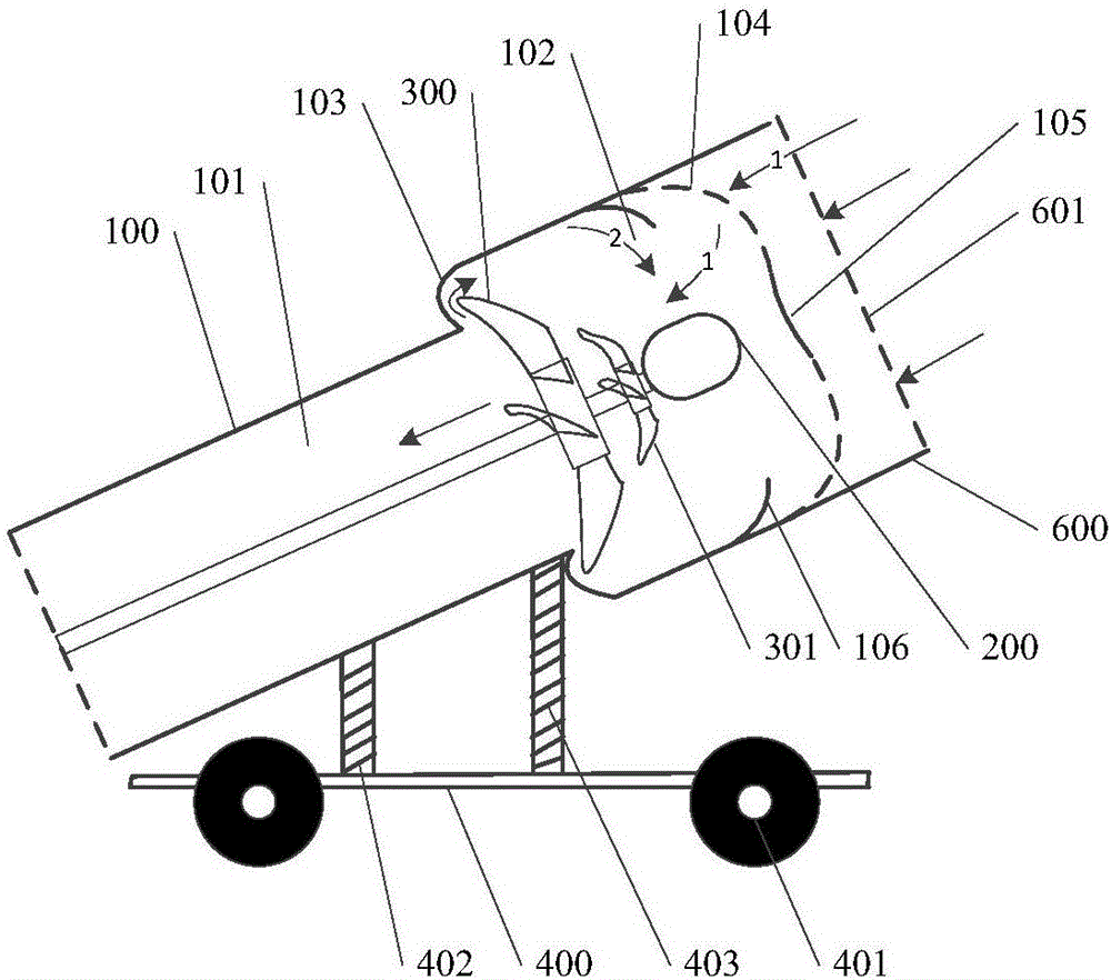
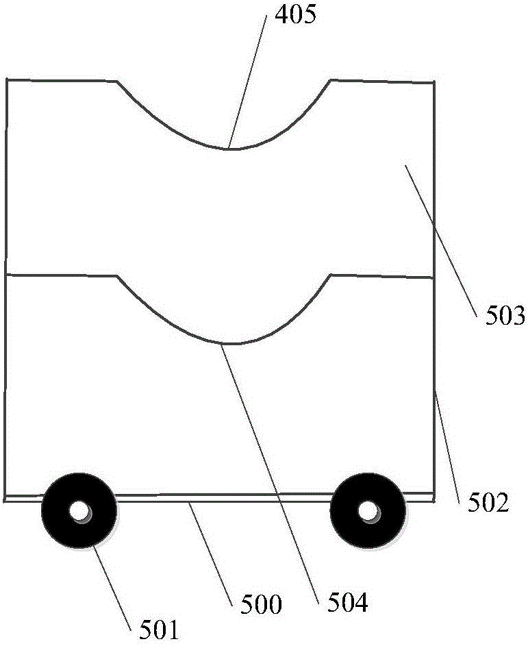
[0032] Such as figure 1 and figure 2 As shown, the present invention provides a special axial flow fan for collecting fallen leaves in gardening, including:

[0033]The car body includes a car board 500, which is a "U"-shaped board body; a wheel body 501, which is rolled on the lower end surface of the car board; a first support plate 502 and a second support plate 503, which are mutually Parallel and vertically arranged on the vehicle plate; a first semicircular notch 504 and a second semicircular notch 505, which are respectively arranged in the middle of the upper ends of t...


PUM

PropertyMeasurementUnit
Cross section diameteraaaaaaaaaa

Abstract

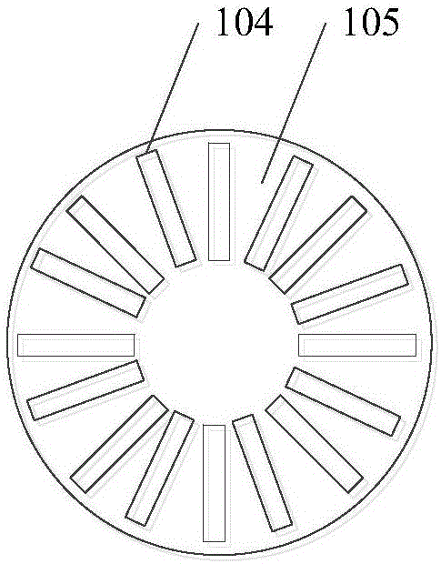
The invention discloses a horticultural special axial flow fan for collecting fallen leaves. The horticultural special axial flow fan for collecting fallen leaves comprises a vehicle body, a housing, a second chamber, a transition section and a first chamber, a plurality of air inlet holes, a motor and a wind wheel, a wind guiding ring and a filter cabin, wherein the housing is obliquely arranged on the vehicle body; the second chamber, the transition section and the first chamber are formed from one end to the other end of the housing; the plurality of air inlet holes are annularly and uniformly formed in the end surface of the other end of the housing; the motor and the wind wheel are coaxially arranged in the second chamber; the wind guiding ring is an annular plate body and the radial direction of the wind guiding ring is arc-shaped, the opening of the arc shape faces the first chamber, the large ring end of the wind guiding ring is fixedly arranged on the side wall, close to the housing, of the other end, the small ring end of the wind guiding ring extends toward the tail end of the motor, and the radial length of the wind guiding ring is smaller than 1 / 6 of the cross section diameter of the second chamber. The horticultural special axial flow fan for collecting fallen leaves disclosed by the invention can quickly collect fallen leaves, so that the labor intensity is reduced; moreover, in the using process, the motor of the axial flow fan is synchronously dissipated, so that the service life of the axial flow fan is prolonged.

Description

technical field [0001] The invention relates to an axial flow fan specially used for collecting fallen leaves in gardening. Background technique [0002] In the prior art, an axial flow fan is often used to blow the fallen leaves. However, for the convenience of operation, people often need to carry the blower to collect and blow the fallen leaves, which is very inconvenient to use. In addition, existing axial flow fans generally include a wind wheel and a motor. The middle part of the wind wheel is press-fitted on the outer rotor of the motor with an interference fit. The rotation of the outer rotor of the motor drives the wind wheel to rotate. Axial movement, so that the wind is released in the axial direction. In order to prevent the wind wheel from hurting people when it rotates, a net cover is generally provided to cover the wind wheel to prevent people from touching the wind blades on the wind wheel. The motor on the axial flow fan is arranged on the air inlet duct of...

Claims


Application Information

Patent Timeline
IPC IPC(8): F04D25/08F04D29/00F04D29/58
CPCF04D25/082F04D29/002F04D29/5806
Inventor 卢璐娇
Owner 卢璐娇
Learn More