Flash tank and refrigerating system

A technology of refrigeration system and flash tank, which is applied in the direction of flash evaporation, refrigerator, refrigeration components, etc., can solve the problems of complex structure of flash tank and so on.

Inactive Publication Date: 2017-05-24
DANFOSS (TIANJIN) CO LTD
View PDF6 Cites 4 Cited by
  • Summary
  • Abstract
  • Description
  • Claims
  • Application Information

AI Technical Summary

Problems solved by technology

However, in existing refrigeration systems, the structure of the flash tank is often complex, and complex control logic and expensive hardware are often required to control the flash tank and the system

Method used


Image

  • Flash tank and refrigerating system
  • Flash tank and refrigerating system
  • Flash tank and refrigerating system

Examples


Embodiment Construction

[0032] The technical solutions of the present invention will be further specifically described below through the embodiments and in conjunction with the accompanying drawings. In the specification, the same or similar reference numerals designate the same or similar components. The following description of the embodiments of the present invention with reference to the accompanying drawings is intended to explain the general inventive concept of the present invention, but should not be construed as a limitation of the present invention.

[0033] In addition, in the following detailed description, for purposes of explanation, numerous specific details are set forth in order to provide a comprehensive understanding of the embodiments of the present disclosure. It may be evident, however, that one or more embodiments may be practiced without these specific details. In other instances, well-known structures and devices are shown in diagrammatic form to simplify the drawings.

[0...


PUM


Abstract

The invention discloses a flash tank which comprises an inlet, a first outlet, a second outlet and a pre-expansion element. Fluid flows into the flash tank from the inlet. The first outlet is located in the top of the flash tank. The second outlet is located in the bottom of the flash tank. The pre-expansion element is integrated in the inlet of the flash tank and is used for pre-expanding fluid flowing into the inlet of the flash tank. In the flash tank, the pre-expansion element used for pre-expanding a refrigerant flowing into the inlet of the flash tank is integrated in the inlet of the flash tank, and therefore an independent throttling valve does not need to be arranged in a fluid inlet pipeline connected with the inlet of the flash tank and the throttling valve does not need to be independently controlled; and thus, the structure of a refrigerating system and control over the refrigerating system are simplified, and the cost is reduced. In addition, the invention further discloses the refrigerating system comprising the above flash tank.

Description

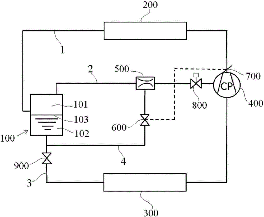
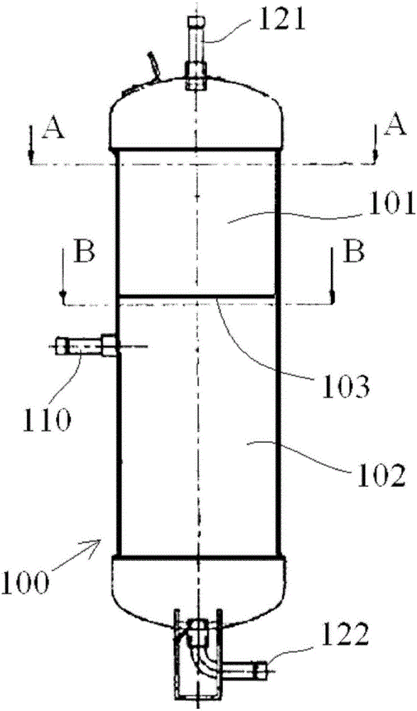
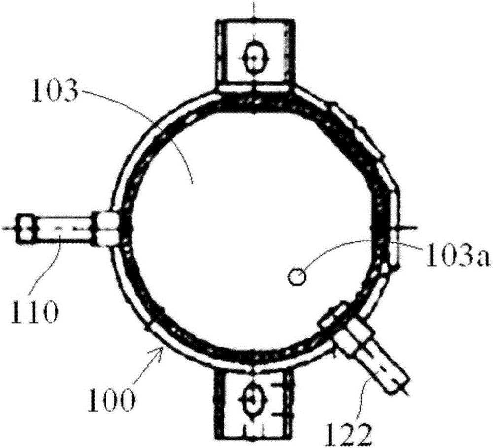
technical field [0001] The invention relates to the technical field of refrigeration, in particular to a flash tank and a refrigeration system comprising the flash tank. Background technique [0002] In the refrigeration system, in order to improve the cooling capacity and refrigeration efficiency, a flash tank is often introduced. However, in existing refrigeration systems, the structure of the flash tank is often complicated, and complex control logic and expensive hardware are often required to control the flash tank and the system. Contents of the invention [0003] The purpose of the present invention is to solve at least one aspect of the above-mentioned problems and deficiencies in the prior art. [0004] An object of the present invention is to provide a flash tank and a refrigeration system comprising the same, wherein a pre-expansion element for pre-expanding the refrigerant flowing into the inlet of the flash tank is integrated in the inlet of the flash tank, ...

Claims


Application Information

Patent Timeline
Patent Type & Authority Applications(China)
IPC IPC(8): F25B41/04B01D3/06F25B41/20
Inventor 董颖张乐平刘鹏苏音迪克欧·瑟达
Owner DANFOSS (TIANJIN) CO LTD
Why Eureka
Try Eureka