Gel battery and production method thereof

A colloidal battery and battery technology, applied in the direction of lead-acid batteries, battery components, lead-acid battery construction, etc., can solve the problems of high process requirements, difficult to achieve penetration and sealing, etc., to achieve efficient glue filling process and consistent products Good performance and reliable sealing effect

Active Publication Date: 2017-05-24
CHAOWEI POWER CO LTD
View PDF3 Cites 1 Cited by
  • Summary
  • Abstract
  • Description
  • Claims
  • Application Information

AI Technical Summary

Problems solved by technology

This structure can be applied to the internal formation of acid-absorbing separator batteries to achieve forced acid circulation on the upper and lower sides of the battery to improve formation and production efficiency. However, this patent is realized on the tank and cover, and the process requirements are relatively high. The tank and cover It is difficult to achieve penetration and sealing between acid holes

Method used


Image

  • Gel battery and production method thereof
  • Gel battery and production method thereof
  • Gel battery and production method thereof

Examples


Embodiment 1

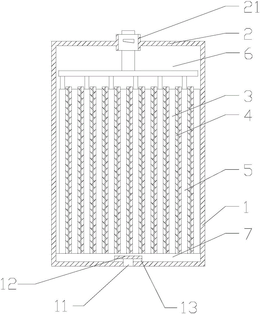
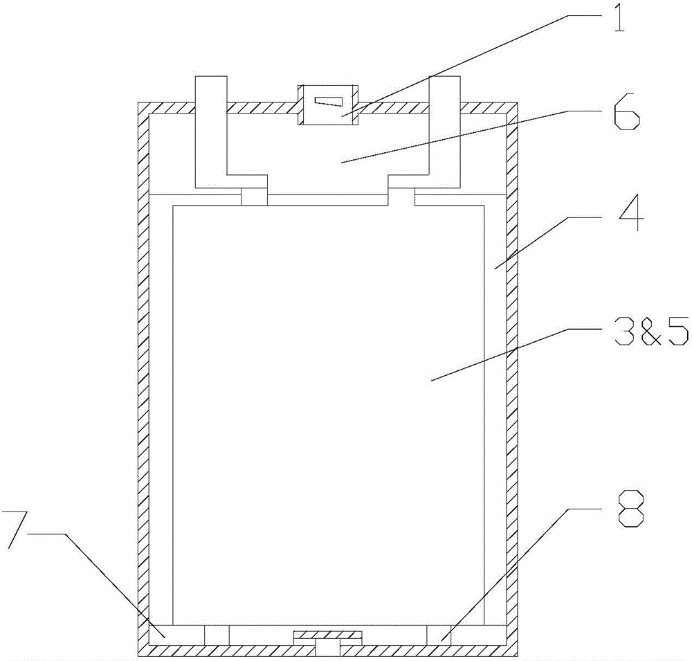
[0057] Such as figure 1 , figure 2 As shown, a colloidal battery includes a battery container 1 , a battery cover 2 and an electrode group disposed in the battery container.

[0058] The electrode group includes stacked positive plates 3 , composite separators 4 and negative plates 5 . The composite separator is composed of a glass wool separator 41 and a microporous PE separator 42 . Such as Figure 5 As shown, in this embodiment, the composite separator has a three-layer structure: microporous PE separator-glass wool separator-microporous PE separator.

[0059] A safety valve hole 21 is provided on the battery cover, and an upper reserved space 6 is provided between the safety valve hole and the electrode group.

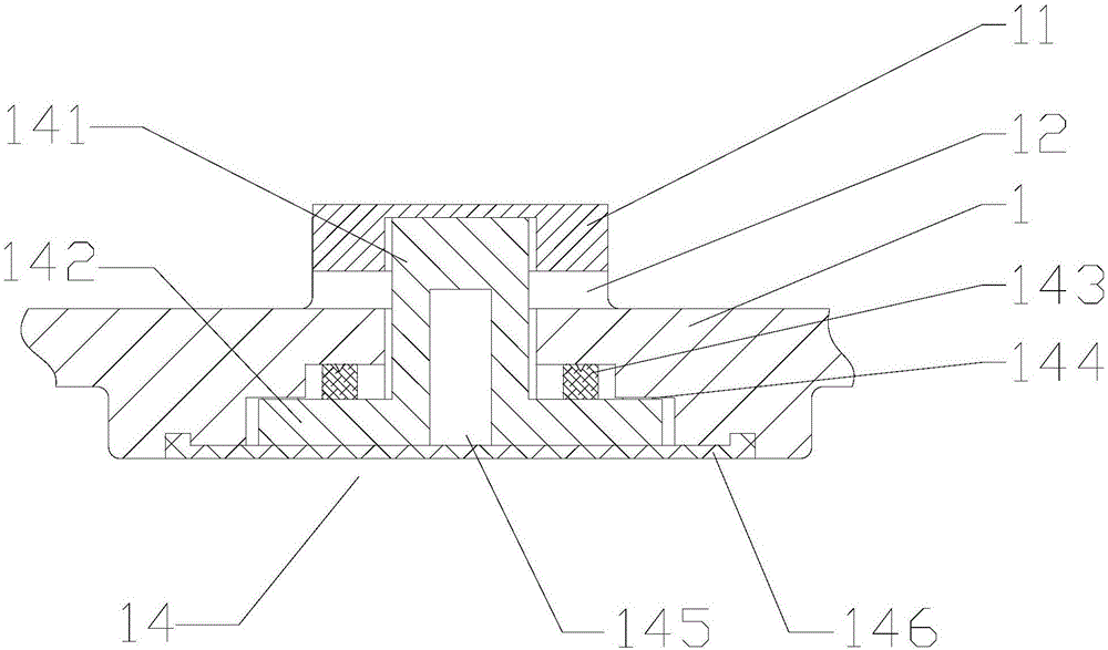
[0060] Such as image 3 , 4 As shown, the bottom of the battery tank is provided with a liquid injection hole 11; a lower reserved space 7 is provided between the bottom of the battery tank and the electrode group; a liquid injection hole is provided on the ...

Embodiment 2

[0064] Such as figure 1 As shown, a colloidal battery includes a battery container 1 , a battery cover 2 and an electrode group disposed in the battery container.

[0065] The electrode group includes stacked positive plates 3 , composite separators 4 and negative plates 5 . The composite separator is composed of a glass wool separator 41 and a microporous PE separator 42 . Such as Image 6 As shown, in this embodiment, the composite separator has a three-layer structure: glass wool separator-microporous PE separator-glass wool separator.

[0066] A safety valve hole 21 is provided on the battery cover, and an upper reserved space 6 is provided between the safety valve hole and the electrode group.

[0067] Such as image 3 , 4 As shown, the bottom of the battery tank is provided with a liquid injection hole 11; a lower reserved space 7 is provided between the bottom of the battery tank and the electrode group; a liquid injection hole is provided on the inner wall of the ...

Embodiment 3

[0071] The difference between this embodiment and embodiment 1 is: as Figure 7 As shown, in this embodiment, the composite separator has a two-layer structure.


PUM

PropertyMeasurementUnit
specific surface areaaaaaaaaaaa
densityaaaaaaaaaa

Abstract

The invention relates to the field of lead-acid storage batteries and discloses a gel battery and a production method thereof. The gel battery comprises a battery case, a battery cover and a plate pack arranged in the battery case, wherein the plate pack comprises positive electrode plates, composite separators and negative electrode plates which are arranged in a laminating manner; each composite separator is formed by overlapping a glass fiber separator and a microporous PE separator; a safe valve hole is formed in the battery cover; an upper reservation space is formed between the safe valve hole and the plate pack; an electrolyte injecting hole is formed in the bottom of the battery case; a lower reservation space is formed between the bottom of the battery case and the plate pack; an electrolyte injecting hole cover is arranged at a part, positioned above the electrolyte injecting hole, of the inner wall of the bottom of the battery case; at least two acid through holes are formed between the electrolyte injecting hole cover and the inner wall of the bottom of the battery case; a sealing plug is arranged in the liquid injecting hole. The gel battery disclosed by the invention can apply ordinary separators and basically keeps an original appearance of the battery; the gel battery has the advantages of simple structure, reliable sealing and easiness for production; an internalizing process and a glue filling process of the gel battery disclosed by the invention are more efficient; a prepared product is better in consistency.

Description

technical field [0001] The invention relates to the field of lead-acid batteries, in particular to a gel battery and a production method thereof. Background technique [0002] The separators of gel batteries with a gel concentration exceeding 5% are mostly made of plastic or resin porous separators, which are complex in process and high in cost. If other common separators are used as separators for colloidal batteries, there will be two technological problems of difficulty in filling glue and forming difficulties. [0003] The application number is CN201420113592.3, and the applicant is Chaowei Power Co., Ltd. The patent discloses a colloidal battery with its own acid cycle and acid pumping structure. This structure can be applied to the internal formation of acid-absorbing separator batteries to achieve forced acid circulation on the upper and lower sides of the battery to improve formation and production efficiency. However, this patent is realized on the tank and cover, ...

Claims


Application Information

Patent Timeline
Patent Type & Authority Applications(China)
IPC IPC(8): H01M10/12H01M2/36H01M2/12
CPCH01M10/12H01M50/325H01M50/60H01M50/636Y02E60/10Y02P70/50
Inventor 沈浩宇
Owner CHAOWEI POWER CO LTD
Why Eureka
Try Eureka