Antenna performance optimization method and system

An optimization method and antenna technology, applied in transmission systems, transmission monitoring, electrical components, etc., can solve problems such as channel radio frequency index deterioration

Active Publication Date: 2017-05-24
YULONG COMPUTER TELECOMM SCI (SHENZHEN) CO LTD
View PDF4 Cites 5 Cited by
  • Summary
  • Abstract
  • Description
  • Claims
  • Application Information

AI Technical Summary

Problems solved by technology

If the power of the entire frequency band is increased, on the one hand, the RF current of the mobile phone wi

Method used


Image

  • Antenna performance optimization method and system
  • Antenna performance optimization method and system
  • Antenna performance optimization method and system

Examples


Embodiment Construction

[0048] In order to make the object, technical solution and advantages of the present invention clearer, the present invention will be described in detail below in conjunction with the accompanying drawings and specific embodiments.

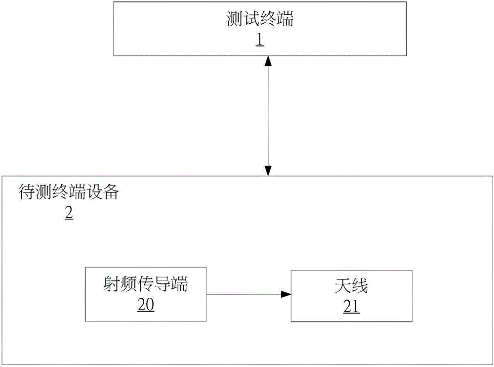
[0049] refer to figure 1 As shown, it is a schematic diagram of an application environment of a preferred embodiment of the antenna performance optimization method of the present invention.

[0050] In a preferred embodiment of the present invention, the antenna performance optimization method is executed by a test terminal 1, and is used for calibrating the terminal device 2 to be tested, so that the antenna 21 of the terminal device 2 to be tested transmits in the same frequency band. The power (totalradiation power, TRP) index is not up to standard. For example, in the case of some poor channels at this frequency, calibration compensation is performed on the radio frequency conducting end 20 of the terminal device 2 to achieve the coupling of t...


PUM


Abstract

The invention provides an antenna performance optimization method. The method comprises the following steps: measuring the radio frequency conduction power and transmitting power of a radio frequency conduction terminal in a to-be-detected terminal device and a coupling end of an antenna on multiple channels of a frequency band; calculating the power dissipation of the channels of the frequency band according to the radio frequency conduction power and the transmitting power; calculating compensation values of the channels according to the power dissipation of the channels; calculating actual radio frequency conduction power of the radio frequency conduction terminal on each channel; and transmitting the actual radio frequency conduction power of each channel to the to-be-detected terminal device, so that the radio frequency conduction terminal of the to-be-detected terminal device performs radio frequency conduction according to the actual radio frequency conduction power of each channel. The invention further provides an antenna performance optimization system. By adoption of the antenna performance optimization method and system provided by the invention, the radio frequency conduction terminal of the to-be-detected terminal device is calibrated and compensated, so that the power of the same frequency band of the coupling end of the antenna is smooth.

Description

technical field [0001] The invention relates to the field of mobile communication, in particular to an antenna performance optimization method and an antenna performance optimization system. Background technique [0002] Due to the limitations of mobile phone structure and materials (metal back shell), etc., it is more and more difficult to debug mobile phone antennas. Especially for mobile phones with metal back shells, due to the influence of metal, it is more difficult to debug the antenna, and the efficiency of the antenna at different frequencies is inconsistent. Click on the possibility of intermittent call sound or even dropped calls. [0003] The transmit power (total radiation power, TRP) index of the antenna is not up to the standard, and sometimes it is necessary to increase the conducted radio frequency to make up for it. For the Qualcomm platform, if it is the same frequency band, it can be solved by modifying the NV to increase the power of the entire frequen...

Claims


Application Information

Patent Timeline
IPC IPC(8): H04B17/309H04B17/10H04B17/11
CPCH04B17/102H04B17/11H04B17/309
Inventor 信哲鑫李双
Owner YULONG COMPUTER TELECOMM SCI (SHENZHEN) CO LTD
Why Eureka
Try Eureka