Scintillator panel, radiation detecting apparatus, and radiation detection system

a technology of radiation detection apparatus and scintillator, which is applied in the field of scintillator, can solve the problems of deteriorating production efficiency, increasing costs, and taking a long time to form the insulative layer

Inactive Publication Date: 2006-09-26
CANON KK
View PDF12 Cites 6 Cited by
  • Summary
  • Abstract
  • Description
  • Claims
  • Application Information

AI Technical Summary

Benefits of technology

[0015]Further another object of the invention is to provide a l

Problems solved by technology

When the phosphor layer of the cylindrical crystal is evaporation-deposited onto the warped substrate, since it is difficult to handle the supporting substrate in the case of setting the supporting substrate into an evaporation depositing apparatus and a defect occurs easily in the phosphor layer, there is a case where production efficiency deteriorates.
If an insulative layer is formed between the surface of the amorphous carbo

Method used


Image

  • Scintillator panel, radiation detecting apparatus, and radiation detection system
  • Scintillator panel, radiation detecting apparatus, and radiation detection system
  • Scintillator panel, radiation detecting apparatus, and radiation detection system

Examples


embodiments

(Embodiments)

[0038]The invention will be described in detail hereinbelow with reference to the drawings.

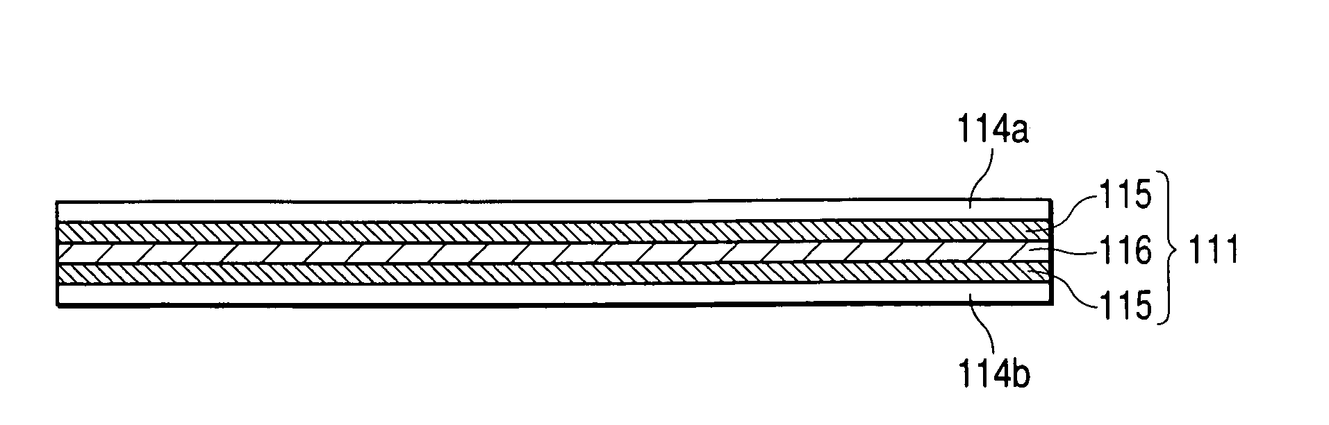
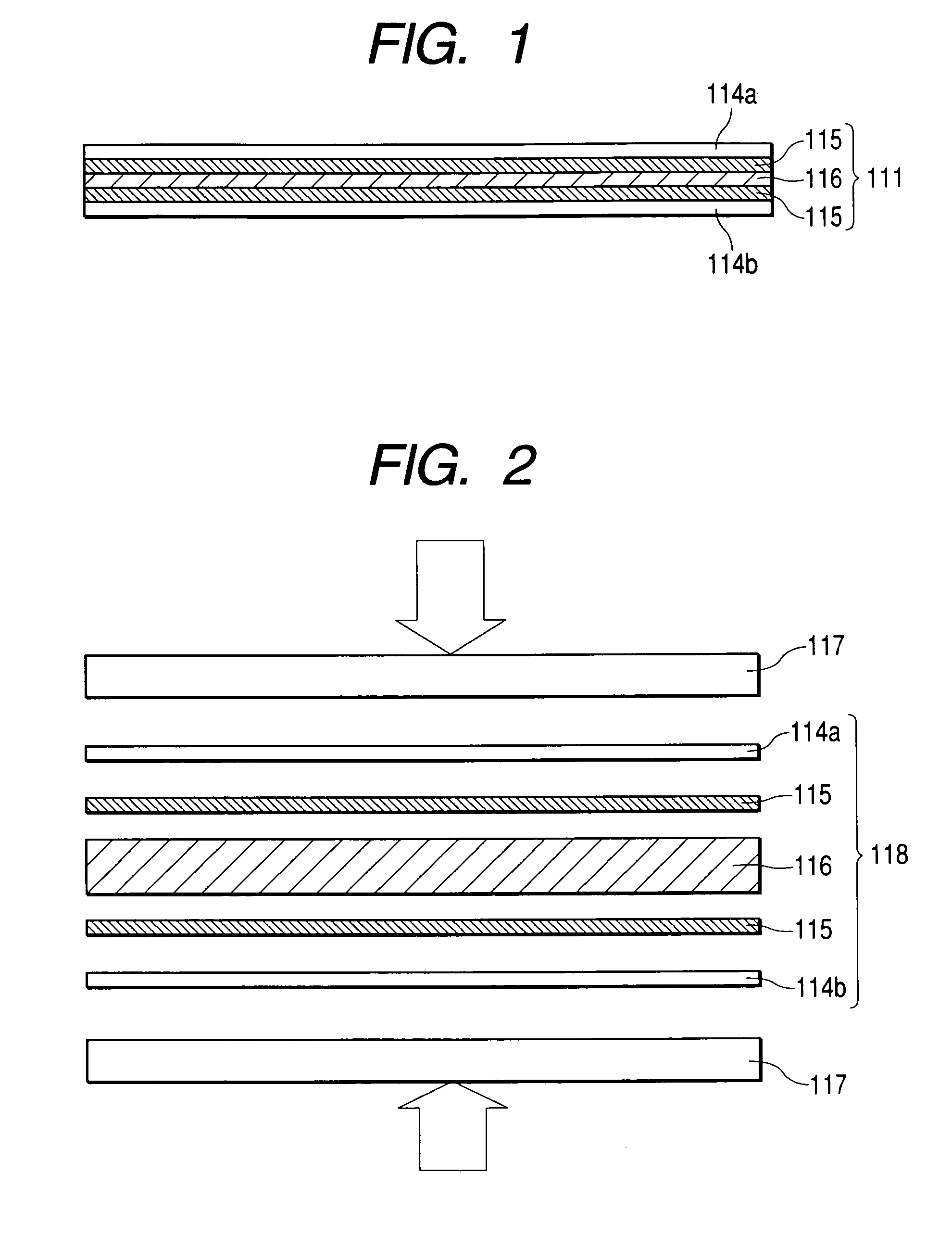
[0039]FIG. 1 is a cross sectional view showing an embodiment of a supporting substrate in a scintillator panel of the invention. FIG. 2 is a diagram showing a manufacturing method of the supporting substrate in the scintillator panel of the invention.

[0040]Reference numeral 111 denotes a supporting substrate; 114a and 114b moisture-proof metal foils; 115 non-conductive layers; and 116 a rigidity holding layer. In the supporting substrate 111, the rigidity holding layer 116 is sandwiched by the two non-conductive layers 115 and both surfaces of the supporting substrate 111 are substantially non-conductive layers. The rigidity holding layer 116 can be a laminate in a state where it is completely separated like layers or can be also constructed in such a manner that a rigidity holding member exists in the non-conductive layers without a distinct boundary and the rigidity holding laye...

example 1

[0062]As shown in FIG. 6, the photodetecting portions (pixel portions) 102 are formed onto the glass substrate 101 by thin semiconductor films made of amorphous silicon. A first protective layer 105 made of SiNx and, further, a polyimide resin are spin-coated onto them and hardened at 200° C. for 6 hours and a second protective layer 106 is formed, thereby manufacturing the photodetector 100.

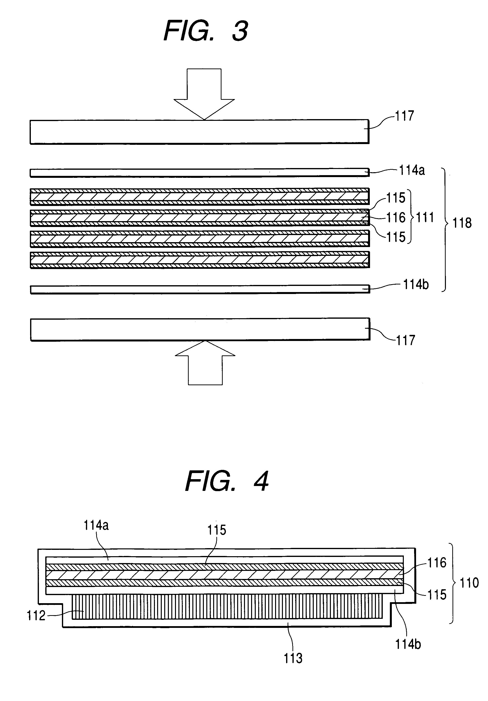
[0063]Subsequently, aromatic polyimide precursors having a thickness of 5 μm and serving as non-conductive layers 115 are coated onto both surfaces of an aromatic polyimide resin having a thickness of 0.5 mm and serving as a rigidity holding layer 116. Aluminum foils having a thickness of 20 μm and serving as moisture-proof metal foils 114a and 114b are laminated onto the surfaces of the aromatic polyimide precursors, pressed, and thereafter, pressed with heat at 270° C., thereby molding the supporting member 118. Upon molding of the supporting member 118, the supporting member 118 is molded by ...

example 2

[0067]The photodetector 100 is manufactured in a manner similar to Example 1.

[0068]The phosphor layer 112 of the columnar crystal made of CsI:Tl is formed onto the surface of the moisture-proof metal foil 114b of the molded supporting member 118 in a manner similar to Example 1. After that, the top face and the side surfaces of the phosphor layer 112 and the surfaces and the edge surfaces other than the region where the phosphor layer 112 is formed on the side of the supporting member 118 where the phosphor layer 112 is formed excluding the moisture-proof metal foil 114a on which the phosphor layer 112 is not formed are coated with the moisture resistant protective layer 113 comprising the organic film made of polyparaxylylene by the CVD method, thereby obtaining the scintillator panel 110.

[0069]The obtained scintillator panel 110 is adhered to the photodetector 100 in a manner similar to Example 1, thereby obtaining the radiation detecting apparatus.

[0070]The radiation detecting ap...


PUM


Abstract

To provide a scintillator panel in which uniform photoelectric converting efficiency is obtained and an image of a high sensitivity and a high sharpness is obtained, a scintillator panel has: a phosphor layer for converting a radiation into light; and a supporting member having a supporting substrate having radiation permeability for supporting the phosphor layer, wherein the supporting substrate is formed by laminating non-conductive layers for assuring non-conductivity of a surface which supports the phosphor layer of the supporting substrate and non-conductivity of an opposite surface which faces the surface and a rigidity holding layer for assuring rigidity of the supporting substrate. Further, moisture-proof metal foils are laminated onto the surface and the opposite surface of the supporting substrate. The panel further includes a moisture resistant protective layer which covers the phosphor layer and the supporting member.

Description

BACKGROUND OF THE INVENTION[0001]1. Field of the Invention[0002]The invention relates to a scintillator panel. Further, the invention relates to a scintillator panel for a radiation detecting apparatus which is used for a medical diagnosing apparatus, a non-destructive inspecting apparatus, or the like and, more particularly, to a scintillator panel for a radiation detecting apparatus which is used for X-ray photographing or the like. In the specification, explanation will be made on the assumption that electromagnetic waves such as X-ray, α-ray, β-ray, γ-ray, and the like are also included in the radiation.[0003]2. Related Background Art[0004]Hitherto, an X-ray film system having a fluorescent screen having an X-ray phosphor therein and a duplicated sensitive agent has generally been used for photographing an X-ray picture. However, in recent years, a digital radiation detecting apparatus having an X-ray phosphor layer and a 2-dimensional photodetector has advantages that image cha...

Claims


Application Information

Patent Timeline
IPC IPC(8): G01T1/20G01T1/02G01T1/161G01T1/24
CPCG01T1/161G01T1/026
Inventor OGAWA, YOSHIHIRO
Owner CANON KK
Why Eureka
Try Eureka