Lost motion assembly in a valve bridge for use with a valve train comprising a hydraulic lash adjuster

A technology for slack adjusters, components, applied in the direction of engine components, machines/engines, non-mechanically actuated valves, etc., which can solve the problems of occupying available gaps, catastrophic damage to engines, excessive extension of hydraulic slack adjusters, etc.

Active Publication Date: 2017-05-24
JACOBS VEHICLE SYST
View PDF5 Cites 11 Cited by
  • Summary
  • Abstract
  • Description
  • Claims
  • Application Information

AI Technical Summary

Problems solved by technology

[0005] However, if a hydraulic slack adjuster is used in connection with a lost motion component, there is a risk that the hydraulic slack adjuster will take up the available clearance during the lost motion cycle, resulting in

Method used


Image

  • Lost motion assembly in a valve bridge for use with a valve train comprising a hydraulic lash adjuster
  • Lost motion assembly in a valve bridge for use with a valve train comprising a hydraulic lash adjuster
  • Lost motion assembly in a valve bridge for use with a valve train comprising a hydraulic lash adjuster

Examples


Embodiment Construction

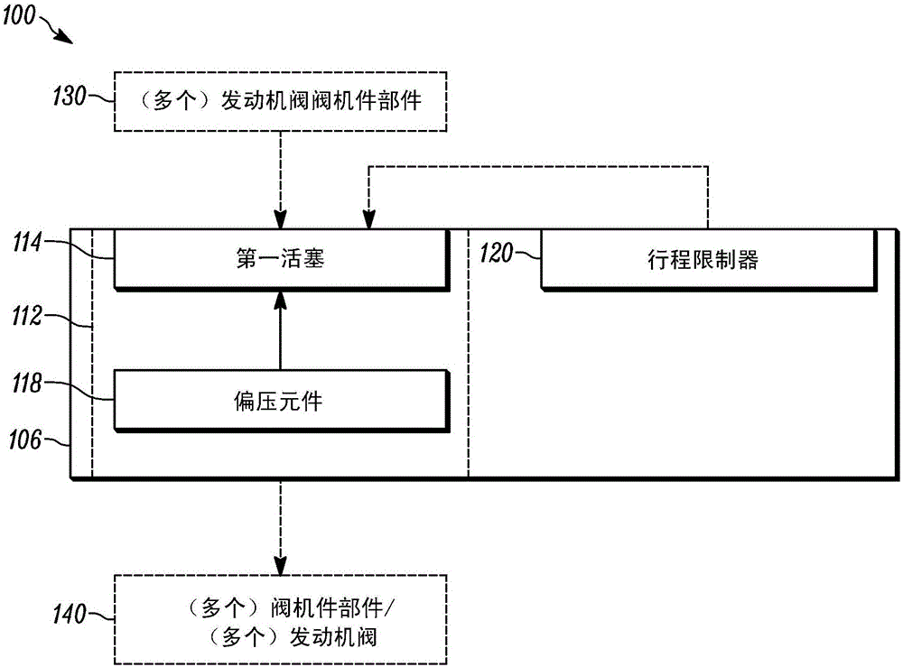
[0022] see now figure 1 , the lost motion assembly 100 according to the present disclosure includes a lost motion housing 106 having a first piston cylinder 112 formed therein and a first piston 114 disposed in the first piston cylinder 114 . In general, the lost motion housing 106 may be embodied by any component of the valve train (eg, pushrod, rocker arm, valve bridge, etc.). However, for purposes of illustration, various embodiments are described in detail below in which the lost motion housing 106 is embodied by a valve bridge. As is known in the art, the first piston 114 may be configured (as shown in the various embodiments below), selective application of hydraulic fluid thereto allows the first piston 114 to switch between the operating mode or another mode. Alternate between the mode of operation in which all valve actuation motions applied thereto (including any auxiliary valve actuation motions) are caused to be transmitted through, and the other mode in which som...


PUM


Abstract

In an internal combustion engine comprising two or more engine valves that receive valve actuation motions from a valve actuation motion source via a valve train, which valve train comprises a hydraulic lash adjuster, an apparatus for valve actuation comprises a valve bridge and a lost motion assembly disposed therein. The lost motion assembly comprises a first piston disposed in a first piston bore formed in the valve bridge. The first piston is configured to operatively connect with a component of the valve train. A biasing element is configured to bias the first piston out of the first piston bore with a first force that is greater than a second force applied to the first piston by the hydraulic lash adjuster. A travel limiter is configured to limit travel of the first piston out of the first piston bore to be no greater than a maximum lost motion distance.

Description

technical field [0001] The present disclosure relates generally to actuation of engine valves in internal combustion engines and more particularly to lost motion assemblies of valve bridges for use in valve trains including hydraulic lash adjusters. Background technique [0002] As is known in the art of internal combustion engines, during a cold start of said engine certain components heat up and may experience thermal expansion. Additionally, over the life of the engine, engine components may wear and thereby change size and shape. The engine's poppet valve (engine valve) and the systems used to operate it (valvework) are exposed to significant temperature variations and potential wear, and therefore, these systems must account for thermal expansion and other conditions that may affect the actuation of the engine valves. Phenomenon. One technique to accommodate thermal expansion, etc. is between an engine valve (or a valve bridge spanning two or more engine valves) and t...

Claims


Application Information

Patent Timeline
IPC IPC(8): F01L1/14F01L1/26F01L9/02F01L9/12F01L9/10
CPCF01L1/24F01L13/06F01L2013/001F01L1/14F01L1/26F01L9/12F01L9/10
Inventor J·巴尔特鲁基
Owner JACOBS VEHICLE SYST
Why Eureka
Try Eureka