Composite pressure forming device and forming method for high-gloss metal sheet

A technology of thin metal plates and forming devices, which is applied in forming tools, feeding devices, positioning devices, etc., can solve the problems of difficult accurate transmission of processing references, unstable dimensions, springback of semi-finished parts, etc., to eliminate optical distortion of product appearance and Dimensional instability defects, the effect of improving production efficiency and yield, and reducing the number of tooling

Active Publication Date: 2018-10-02
FUJIAN FUYAO AUTOMOTIVE TRIM SYST CO LTD
View PDF8 Cites 0 Cited by
  • Summary
  • Abstract
  • Description
  • Claims
  • Application Information

AI Technical Summary

Problems solved by technology

[0002] At present, the interior and exterior decoration parts of automobiles and locomotives are more and more widely used and more diverse. Most of these parts are made of high-gloss magnesium, aluminum alloy and stainless steel sheets. The surface characteristics of these products are not obvious, and they are required to be very smooth and smooth. And there must be a high visual decorative effect. The raw materials used for parts are thin and narrow, and the quality of the manufacturing process is not easy to control. The semi-finished product has serious warping deformation and dimensional inconsistency, and is accompanied by unequal processing negative angles.
Because the traditional manufacturing process has many processes, the thin and long process parts lead to springback, warping deformation, and dimensional inconsistency of semi-finished parts, which makes it difficult to accurately transfer the processing standards between processes, resulting in a low pass rate of parts and low production efficiency. Very low, high manufacturing cost, serious waste, mainly reflected in defects such as appearance light distortion and dimensional instability

Method used


Image

  • Composite pressure forming device and forming method for high-gloss metal sheet
  • Composite pressure forming device and forming method for high-gloss metal sheet
  • Composite pressure forming device and forming method for high-gloss metal sheet

Examples


Embodiment Construction

[0032] The present invention will be further described below in conjunction with the accompanying drawings and specific embodiments.

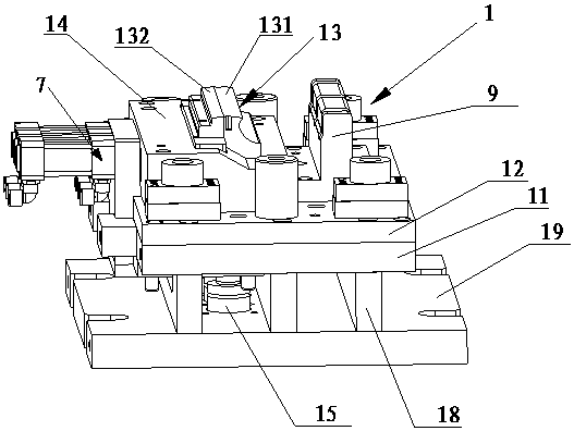
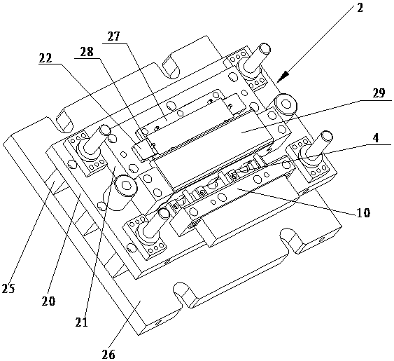
[0033] Such as Figure 1~3As shown, a composite pressure forming device for high-gloss metal sheets in this embodiment includes an upper mold 1 and a lower mold 2 respectively installed on the upper and lower tables of the press, and the upper mold 1 and the lower mold 2 are opposite to each other up and down. Setting; the upper mold 1 includes an upper template 11, an upper backing plate 12 and an upper frame body 14 arranged up and down in sequence, and a vertical gap is provided in the middle of the upper backing plate 12 and the upper frame body 14, and the inside of the gap A punch assembly 13 is movable, and the punch assembly 13 is driven by the first nitrogen spring 15; the lower mold 2 includes a lower template 20, a lower frame 21 arranged on the lower template 20, and a movable card arranged on The stripping plate 22 that is used to...


PUM


Abstract

The invention relates to a compound pressure molding device for highlight sheet metal and a molding method of the compound pressure molding device. The compound pressure molding device comprises an upper die and a lower die which are mounted on an upper table surface and a lower table surface of a press correspondingly, wherein the upper die and the lower die are oppositely arranged up and down; the upper die comprises an upper template, an upper backing plate and an upper frame body which are sequentially arranged up and down, a vertical notch is formed in the middle of each of the upper backing plate and the upper frame body in a penetrating manner, and a male die component is movably arranged in the notches and driven by a first nitrogen spring; and the lower die comprises a lower template, a lower frame body arranged on the lower template and a stripper plate movably clamped on the lower frame body, as well as a first flanging knife block and a second flanging knife block which are arranged on the left side and the right side of the stripper plate correspondingly, the second flanging knife block is fixed on a slider, the slider is movably arranged on the lower template, and the bottom surface of the male die component and the top surface of the stripper plate correspond to each other up and down. The production efficiency and the yield are improved through reducing procedures and unstable positioning of the procedures.

Description

technical field [0001] The invention relates to a compound pressure forming device and a forming method for high-gloss metal thin plates, mainly used for automobiles, locomotives and other interior and exterior stainless steel or magnesium, aluminum alloy thin plate parts. Background technique [0002] At present, the interior and exterior decoration parts of automobiles and locomotives are more and more widely used and more diverse. Most of these parts are made of high-gloss magnesium, aluminum alloy and stainless steel sheets. The surface characteristics of these products are not obvious, and they are required to be very smooth and smooth. And there must be a high visual decorative effect. The raw materials used for parts are thin and narrow, and the quality of the manufacturing process is not easy to control. The semi-finished product has serious warping deformation and dimensional inconsistency, and is accompanied by unequal processing negative angles. Because the tradit...

Claims


Application Information

Patent Timeline
Patent Type & Authority Patents(China)
IPC IPC(8): B21D5/00B21D5/02B21D37/10B21D43/00
CPCB21D5/002B21D5/004B21D5/02B21D37/10
Inventor 倪慨宇吴滨
Owner FUJIAN FUYAO AUTOMOTIVE TRIM SYST CO LTD
Why Eureka
Try Eureka