Robot double-arm self-balance method and robot

A robot and self-balancing technology, applied in the field of robotics, can solve the problems of falling objects on the arms and the safety of the objects in the arms cannot be guaranteed, and achieve the effect of rapid response

Active Publication Date: 2017-05-31
GUANGDONG UNIV OF TECH
8 Cites 3 Cited by

AI-Extracted Technical Summary

Problems solved by technology

[0005] The embodiment of the present invention provides a robot double-arm self-balancing method and a robot, which solves the problem that in the prior art, the service robot cannot keep the balance of the d...

Method used

A kind of robot double-arm self-balancing method is provided in the embodiment of the present invention, the robot double-arm is carried out mathematical modeling, the mathematical model of establishment is combined with the gyroscope attitude information of robot, generates can quick response, accurate Mathematical model of robotic dual-arm balance. The control method of this bionics-based robot dual-arm self-balancing method is simple. By continuously measuring and supervising the change of the body tilt angle of the robot, the change information can be grasped to reduce the risk caused by uncertainty, and the The mathematical model of the robot is combin...

Abstract

The embodiment of the invention discloses a robot double-arm self-balance method and a robot for solving the technical problems that in the prior art, due to the fact that a service robot bears weights or encounters robot body inclination, the robot cannot keep double arm balance, consequently, objects on the double arms fall down and are damaged, and the safety of the objects on the double arms is not guaranteed. The method of the embodiment comprises the steps that palms are rotated and adjusted to be in a balance state through control over the motor rotation angle of the arms of the robot and according to the inclination angle of a first gyroscope; according to output data, detected in real time, of the first gyroscope and a second gyroscope, whether the robot body inclination angle of the robot is changed or not is judged; and if the robot body inclination angle of the robot is changed, the robot body inclination angle of the robot is calculated, and the arms are vertically moved or the palms are rotated according to the inclination angle.

Application Domain

Manipulator

Technology Topic

GyroscopeService robot +1

Image

  • Robot double-arm self-balance method and robot
  • Robot double-arm self-balance method and robot
  • Robot double-arm self-balance method and robot

Examples

  • Experimental program(1)

Example Embodiment

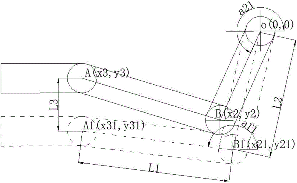
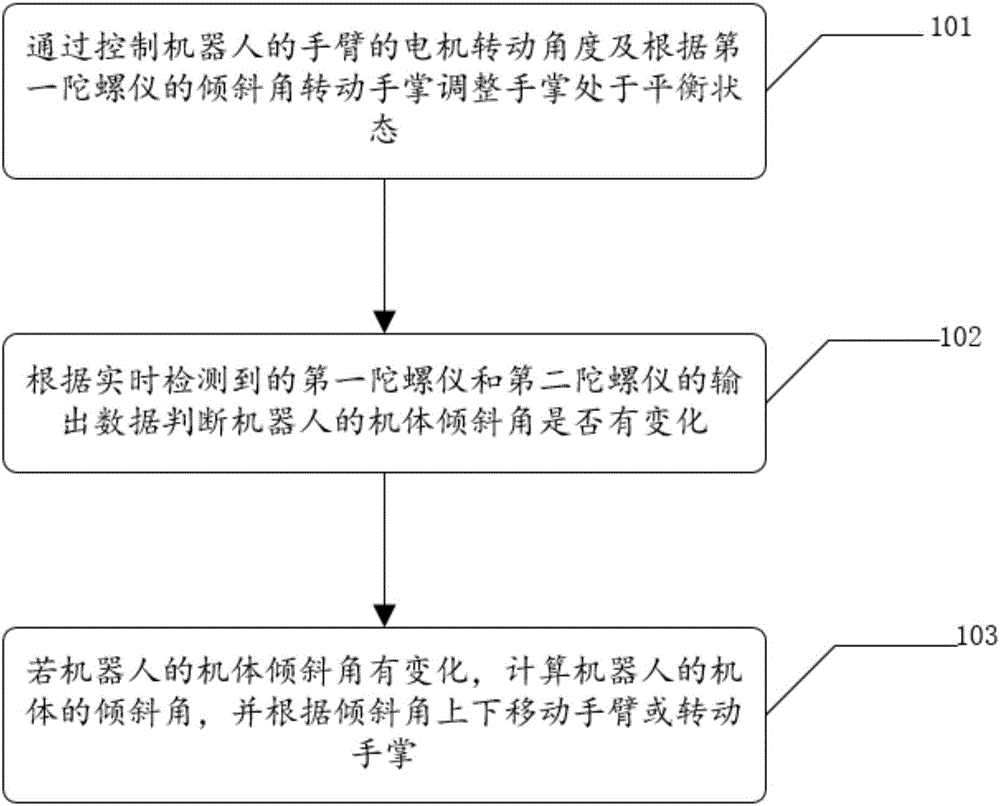
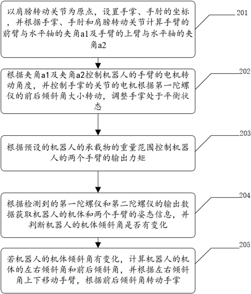
[0045] The embodiment of the present invention provides a dual-arm self-balancing method of a robot and a robot, which are used to solve the problem that the service robot in the prior art cannot maintain the balance of the dual arms due to the load of the service robot or the tilt of the body. It is a technical problem that the safety of the items on the arms cannot be guaranteed due to damage.
[0046] In order to make the objectives, features, and advantages of the present invention more obvious and understandable, the technical solutions in the embodiments of the present invention will be described clearly and completely in conjunction with the accompanying drawings in the embodiments of the present invention. Obviously, the following The described embodiments are only a part of the embodiments of the present invention, rather than all the embodiments. Based on the embodiments of the present invention, all other embodiments obtained by those of ordinary skill in the art without creative work shall fall within the protection scope of the present invention.
[0047] See figure 1 An embodiment of a method for self-balancing robot arms provided by an embodiment of the present invention includes:
[0048] Robots, the robot’s arms include rotatable palm, elbow and shoulder rotating joints;
[0049] The palm is provided with a first gyroscope, and the bottom of the robot is provided with a second gyroscope;
[0050] It should be noted that the rotation joints of the palm, elbow and shoulder of the robot are equipped with drive motors, that is, the two arms of the robot are respectively equipped with three freely controllable drive motors to ensure that the robot's arms can be like the joints of human arms. Move up and down.
[0051] The method steps include: 101. Adjust the palm to be in a balanced state by controlling the motor rotation angle of the arm of the robot and rotating the palm according to the tilt angle of the first gyroscope;
[0052] First, when the robot is at a standstill before starting, adjust the angle of the robot arm by controlling the rotation angle of the motor on the palm, elbow and shoulder rotation joints of the robot arm, and control the rotation of the motor at the palm according to the tilt angle of the first gyroscope To rotate the palm of the robot so that the palm of the robot can be in a horizontal position and reach a balanced state, and the palms of the robot arms can be parallel and at the same height to extend directly in front of the robot, so as to stabilize on the palms of the robot arms Place items such as restaurant trays, food, etc.
[0053] 102. Determine whether the inclination angle of the robot body has changed according to the output data of the first gyroscope and the second gyroscope detected in real time;
[0054] When the robot is traveling, the output data of the first gyroscope on the palm of the robot's arms and the second gyroscope on the bottom of the robot body are detected in real time to determine whether the tilt angle of the robot body changes, that is, the robot is judged Whether there is any situation in which the body of the robot is tilted due to heavy objects or obstacles encountered during the travel.
[0055] 103. If the tilt angle of the robot body changes, calculate the tilt angle of the robot body, and move the arm up and down or rotate the palm according to the tilt angle.
[0056] If the tilt angle of the robot body changes, that is, the body of the robot is tilted, the tilt angle of the robot body is calculated, such as the front and back tilt angle, the left and right tilt angle, etc., according to the nature of the tilt angle, such as moving the arm up and down or turning The palm of the hand is adjusted so that the palm of the robot is always in a balanced state and prevents items and food placed on the palm of the robot from slipping off.
[0057] The above is a detailed description of an embodiment of a method for self-balancing robot dual-arms provided by an embodiment of the present invention, and another embodiment of a method for self-balancing robot dual-arms provided by the present invention will be described in detail below.
[0058] See figure 2 , Another embodiment of a method for self-balancing robot arms provided by an embodiment of the present invention includes:
[0059] 201. Using the shoulder rotation joint as the origin, set the coordinates of the palm and elbow, and calculate the angle a1 between the forearm of the arm and the horizontal axis and the angle a2 between the upper arm of the arm and the horizontal axis according to the rotation joint of the palm, elbow and shoulder;
[0060] First of all, the mathematical model of the robot’s arms can be designed based on bionics, such as image 3 Shown is the arm model of the robot. Among them, A is the palm of the robot, B is the elbow of the robot, and O is the shoulder rotation joint of the robot. You can use the shoulder rotation joint as the origin and the shoulder rotation joint as the coordinate origin to establish a rectangular coordinate system. According to the rectangular coordinates Set the palm and elbow coordinates. The coordinates of A, B and O are A(x3, y3), B(x2, y2) and O(0,0) respectively, and AB=L1, BO=L2, x-axis The included angle with OB is a2. If a rectangular coordinate system is established with B as the origin, the included angle between the x-axis and AB is a1. Therefore, the angle a1 between the forearm of the arm and the horizontal axis and the angle a2 between the upper arm of the arm and the horizontal axis can be calculated according to the rotation joints of the palm, elbow and shoulder, and the dynamics of the arm can be obtained by dynamic analysis according to the structure of the robot arm. The equations and dynamic equations are as follows:
[0061] x2=L2*cos(a2);
[0062] y2=L2*sin(a2);
[0063] x3=L2*cos(a2)+L1*cos(a1);
[0064] y3=L2*sin(a2)+L1*sin(a1);
[0065] Since L1 and L2 are the lengths of the forearm and upper arm respectively, and their lengths are fixed, the coordinates of the palm and elbow, that is, the coordinates of A and B, can be used to easily find the angle a1 between the forearm and the horizontal axis and the upper arm of the arm and The included angle a2 of the horizontal axis.
[0066] 202. Control the motor rotation angle of the arm of the robot according to the included angle a1 and the included angle a2, and control the motor of the palm joint to rotate according to the front and back tilt angle of the first gyroscope, and adjust the palm to be in a balanced state;
[0067] In order to facilitate the palm to be in a balanced state and to balance the force of the robot arm, generally the angle a1 between the forearm and the horizontal axis can be 180°, and the angle a2 between the upper arm of the arm and the horizontal axis can be 225°. Therefore, the motor rotation angle of the robot arm can be controlled according to the included angle a1 and the included angle a2. At the same time, the motor that controls the joints of the palm needs to rotate according to the front and back tilt angle of the first gyroscope to adjust the palm in a balanced state.
[0068] Specifically, such as Figure 4 Shown is the robot arm model when the robot arm moves vertically downward by a distance of L3. When the robot arm moves vertically downward by a distance of L3, A1 (x31, y31) and B1 (x21, y21) are used to represent the coordinates of the palm and elbow after the movement. At this time, the details of the joints of the arm are as follows:
[0069] x31=L2*cos(a2)+L1*cos(a1);
[0070] y31=L2*sin(a2)+L1*sin(a1)-L3;
[0071] Therefore, in order to make the robot arm return to its original position, it is necessary to move the robot arm vertically upward by L3. At this time, the specific data of each joint of the arm is as follows:
[0072] y31=L2*sin(a2)+L1*sin(a1)+L3;
[0073]
[0074] It can be seen that the angle that the shoulder rotation joint (point O) needs to rotate is: a21-a2;
[0075]
[0076] It can be seen that the rotation angle of the elbow joint (point B) is: a11-a1; the rotation of the palm joint (point A) is controlled by the first gyroscope.
[0077] 203. Control the output torque of the two arms of the robot according to the preset weight range of the load of the robot;
[0078] Since the robot cannot know the weight of the objects to be carried in advance, the weight range of the objects can be set on the setting screen of the robot before the transportation, so that the two arms of the robot can be controlled according to the preset weight range of the robot’s load. This allows the robot to output a suitable torque in advance to prevent the robot’s arms from shaking greatly due to sudden weights.
[0079] 204. Obtain posture information of the body and two arms of the robot according to the detected output data of the first gyroscope and the second gyroscope, and determine whether the tilt angle of the robot body has changed;
[0080] When the robot is traveling, the output data of the first gyroscope on the palm of the robot's arms and the second gyroscope on the bottom of the robot body are detected in real time to determine whether the tilt angle of the robot body changes, that is, the robot is judged Whether there is any situation in which the body of the robot is tilted due to heavy objects or obstacles encountered during the travel.
[0081] 205. If the tilt angle of the robot body changes, calculate the left and right tilt angle and the front and back tilt angle of the robot body, move the arm up and down according to the left and right tilt angle, and rotate the palm according to the front and back tilt angle.
[0082] If the tilt angle of the robot body changes, that is, the body of the robot is tilted, the tilt angle of the robot body is calculated, such as the front and back tilt angle, the left and right tilt angle, etc., according to the nature of the tilt angle, such as moving the arm up and down or turning The palm of the hand is adjusted so that the palm of the robot is always in a balanced state and prevents items and food placed on the palm of the robot from slipping off.
[0083] Specifically, when the robot is moving or stationary, the posture of the body can be monitored according to the first gyroscope and the second gyroscope inside the robot body, and the XYZ space can be established according to the posture information detected by the first gyroscope and the second gyroscope. Rectangular coordinate system or polar coordinate. Through coordinate transformation, there are two transformed coordinates. One is the rectangular coordinate system XOZ facing the robot, corresponding to the posture of the left and right sides of the robot, and the other is the rectangular coordinate system established on the side of the robot. YOZ corresponds to the posture of the front and back sides of the robot, and adjusts the balance of the arms according to the posture of the robot.
[0084] If the robot's arms are originally balanced, and the tilt angle of the body suddenly changes, in order to keep the items on the palm safe, the arms must be kept in balance as soon as possible. At this time, the angle of the left and right tilt changes is E, and the angle of the front and back tilt changes is F. The center distance between the arms is L, then the palm joint A of the arm quickly tilts back and forth to the body and rotates the angle F in the opposite direction, so that the palm can quickly remain level. Such as Figure 5 As shown, it is a cross-sectional view of the left and right tilt of the robot body. In order to make the arm less affected by the left and right tilt of the body, the left and right arms of the robot should move up and down at the same time. L3=0.5*L*tan(E). During the up and down movement, the B joint and The rotation angle of the O joint is as before.
[0085] It should be noted that during the movement of the robot, the first gyroscope located in the palm continuously feeds back the posture information of the palm, and the motor of palm joint A will rotate according to the change value of the front and back tilt angle in the posture information of the palm. The value keeps the palm in a horizontal position at all times.
[0086] The embodiment of the present invention provides a dual-arm self-balancing method of the robot, which mathematically models the dual-arms of the robot, and combines the established mathematical model with the posture information of the robot's gyroscope to generate the dual-arms of the robot that can respond quickly and accurately Balance mathematical model. The control method of the dual-arm self-balancing method based on bionics is simple. By continuously measuring and supervising the change of the inclination angle of the robot body, the change information can be grasped to reduce the risk caused by uncertainty. The mathematical model of the robot is combined with the posture information of the gyroscope to adjust the posture of both arms in time to ensure the safety of the items on the palm, so that the robot can drive on inclined or uneven roads. In addition, the range of the weight can be preset to reduce the swing of the robot's arms due to a sudden load, and quickly restore balance.
[0087] The above is a detailed description of another embodiment of a dual-arm self-balancing method of a robot provided by an embodiment of the present invention. The following will describe in detail a robot provided by an embodiment of the present invention.
[0088] See Image 6 , A robot provided by an embodiment of the present invention includes:
[0089] Body, arm and arm self-balancing controller, arm includes rotatable palm, elbow and shoulder rotating joints;
[0090] The palm is provided with a first gyroscope, and the bottom of the body is provided with a second gyroscope;
[0091] The arm self-balancing controller includes: a control module 301, which is used to control the rotation angle of the motor of the robot arm and adjust the palm in a balanced state; the control module 301 includes:
[0092] The calculation unit 3011 is used to set the palm and elbow coordinates with the shoulder rotation joint as the origin, and calculate the angle a1 between the forearm of the arm and the horizontal axis and the upper arm of the arm and the horizontal axis according to the palm, elbow and shoulder rotation joints Included angle a2;
[0093] The control unit 3012 is used to control the motor rotation angle of the robot arm according to the included angle a1 and the included angle a2, and control the motor of the palm joint to rotate according to the front and back tilt angle of the first gyroscope, and adjust the palm to be in a balanced state.
[0094] The preset module 302 is used to control the output torque of the two arms of the robot according to the preset weight range of the robot's load;
[0095] The judging module 303 is used for judging whether the tilt angle of the robot body has changed according to the output data of the first gyroscope and the second gyroscope detected in real time; the judging module includes:
[0096] The judging unit 3031 is configured to obtain posture information of the body and two arms of the robot according to the detected output data of the first gyroscope and the second gyroscope, and judge whether the tilt angle of the robot body changes.
[0097] The adjustment module 304 is used to calculate the inclination angle of the robot body if the inclination angle of the robot body changes, and move the arm up and down or rotate the palm according to the inclination angle; the adjustment module includes:
[0098] The adjustment unit 3041 is used to calculate the left and right tilt angle and the front and back tilt angle of the robot body if the tilt angle of the robot body changes, and move the arm up and down according to the left and right tilt angle, and rotate the palm according to the front and rear tilt angle.
[0099] It should be noted that the palm of the robot is provided with a rubber pad. In order to make the robot arm more stable when carrying objects, a thick soft rubber pad is added to the two palms of the robot arm, which can not only prevent slippage, but also play a role in cushioning and damping.
[0100] Those skilled in the art can clearly understand that, for the convenience and conciseness of the description, the specific working process of the above-described system, device, and unit can refer to the corresponding process in the foregoing method embodiment, which will not be repeated here.
[0101] In the several embodiments provided in this application, it should be understood that the disclosed system, device, and method may be implemented in other ways. For example, the device embodiments described above are merely illustrative. For example, the division of the units is only a logical function division, and there may be other divisions in actual implementation, for example, multiple units or components may be combined or It can be integrated into another system, or some features can be ignored or not implemented. In addition, the displayed or discussed mutual coupling or direct coupling or communication connection may be indirect coupling or communication connection through some interfaces, devices or units, and may be in electrical, mechanical or other forms.
[0102] The units described as separate components may or may not be physically separated, and the components displayed as units may or may not be physical units, that is, they may be located in one place, or they may be distributed on multiple network units. Some or all of the units may be selected according to actual needs to achieve the objectives of the solutions of the embodiments.
[0103] In addition, the functional units in each embodiment of the present invention may be integrated into one processing unit, or each unit may exist alone physically, or two or more units may be integrated into one unit. The above-mentioned integrated unit can be realized in the form of hardware or software functional unit.
[0104] If the integrated unit is implemented in the form of a software functional unit and sold or used as an independent product, it can be stored in a computer readable storage medium. Based on this understanding, the technical solution of the present invention essentially or the part that contributes to the prior art or all or part of the technical solution can be embodied in the form of a software product, and the computer software product is stored in a storage medium , Including several instructions to make a computer device (which may be a personal computer, a server, or a network device, etc.) execute all or part of the steps of the method described in each embodiment of the present invention. The aforementioned storage media include: U disk, mobile hard disk, read-only memory (ROM, Read-Only Memory), random access memory (RAM, Random Access Memory), magnetic disks or optical disks and other media that can store program codes.
[0105] As mentioned above, the above embodiments are only used to illustrate the technical solutions of the present invention, but not to limit them; although the present invention has been described in detail with reference to the foregoing embodiments, those of ordinary skill in the art should understand that: The technical solutions recorded in the embodiments are modified, or some of the technical features are equivalently replaced; these modifications or replacements do not cause the essence of the corresponding technical solutions to deviate from the spirit and scope of the technical solutions of the embodiments of the present invention.

PUM

no PUM

Description & Claims & Application Information

We can also present the details of the Description, Claims and Application information to help users get a comprehensive understanding of the technical details of the patent, such as background art, summary of invention, brief description of drawings, description of embodiments, and other original content. On the other hand, users can also determine the specific scope of protection of the technology through the list of claims; as well as understand the changes in the life cycle of the technology with the presentation of the patent timeline. Login to view more.

Similar technology patents

Total bilirubin detection kit

InactiveCN105586384Agood color renderingRapid response
Owner:VISION BIOLOGICAL TECH HEFEI CO LTD

Method for producing monoacetylated homopiperazine

Owner:大连凯飞精细化工有限公司

Classification and recommendation of technical efficacy words

  • Rapid response

Image display

InactiveUS20050259068A1rapid responsesimple and inexpensive construction
Owner:BRIDGESTONE CORP

Restoration method for organic contaminated soil

InactiveCN102950149ARapid responseGood degradation effect
Owner:WUHAN HUAXINYUAN ENVIRONMENT TECH CO LTD
Why Eureka
Try Eureka