Automatic cutting counting system

An automatic cutting and conveying system technology, applied in the direction of metal processing, etc., can solve the problems of manual counting and low degree of cutting automation

Inactive Publication Date: 2017-05-31
TIANJIN BINHAI ZHONGGUAN RUBBER HOSE
View PDF0 Cites 3 Cited by
  • Summary
  • Abstract
  • Description
  • Claims
  • Application Information

AI Technical Summary

Problems solved by technology

[0004] The purpose of the present invention is to provide an automatic cutting and counting syste

Method used


Image

  • Automatic cutting counting system
  • Automatic cutting counting system
  • Automatic cutting counting system

Examples


Embodiment Construction

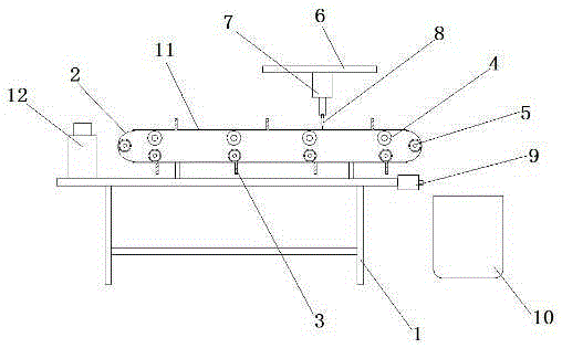
[0015] The invention provides an automatic cutting and counting system, which has the advantages of simple structure, convenient use, high degree of automation, high working efficiency and convenient cutting.

[0016] The technical solutions in the embodiments of the present invention will be described clearly and in detail below in conjunction with the accompanying drawings in the embodiments of the present invention. Obviously, the described embodiments are only part of the embodiments of the present invention, not all of them. Based on the embodiments of the present invention, all other embodiments obtained by persons of ordinary skill in the art without making creative efforts belong to the protection scope of the present invention.

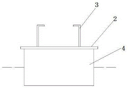
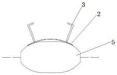
[0017] Such as figure 1 , 2 A kind of automatic cutting and counting system shown in and 3, comprises frame 1, conveyer belt 2, fixed clip 3, cylindrical conveying roller 4, arc conveying roller 5, top plate 6, telescopic cylinder 7, cutter ...


PUM


Abstract

The invention discloses an automatic cutting counting system which comprises a rack, a conveyer belt, a plurality of fixing clamps, cylindrical transferring rollers, arc transferring rollers, a top plate, a telescopic cylinder, a cutting knife, a counter, a collection basket and a knife plate. The rack is provided with the conveyer belt. The cylindrical transferring rollers are arranged at the upper end of the inner side of the conveyer belt, and the arc transferring rollers are arranged at the lower end of the inner side of the conveyer belt which is evenly provided with the fixing clamps. The outer surface of the conveyer belt is provided with the knife plate. The top plate is arranged above the conveyer belt. The lower end of the top plate is provided with the telescopic cylinder. The lower end of the telescopic cylinder is provided with the cutting knife. The counter is arranged on the portion, on the right side of the conveyer belt, of the rack. The right side of the rack is provided with the collection basket. The automatic cutting counting system is simple in structure, convenient to use and high in automation degree and working efficiency, and cutting is facilitated.

Description

technical field [0001] The invention relates to the technical field of auto parts production, and more specifically relates to an automatic cutting and counting system. Background technique [0002] Auto parts need some steel pipes or rubber hoses in the production. The raw materials of these parts are uncut, and they need to be cut into the required size or shape before use. Now, manual cutting is used in production. Manual cutting The work efficiency is very low, unable to meet the needs of production, and the number of cutting needs to be counted one by one, which is time-consuming and laborious, so it is very necessary to solve the above problems. [0003] Therefore, due to the above-mentioned technical defects in the prior art, it is a technical problem to be solved urgently by those skilled in the art. Contents of the invention [0004] The object of the present invention is to provide an automatic cutting and counting system, aiming to solve the problems in the pri...

Claims


Application Information

Patent Timeline
IPC IPC(8): B26D7/28B26D1/08B26D7/06
Inventor 张宝海
Owner TIANJIN BINHAI ZHONGGUAN RUBBER HOSE
Why Eureka
Try Eureka