
Electrocardiogram lead wire retraction and release appliance

A lead wire, electrocardiogram technology, applied in the field of medical devices, can solve the problems of lead wires not entangled with each other and unclear lead wires

Active Publication Date: 2017-05-31
沈阳医学院附属第二医院
View PDF7 Cites 9 Cited by
  • Summary
  • Abstract
  • Description
  • Claims
  • Application Information

AI Technical Summary

Problems solved by technology

[0003] In order to overcome the defects of the prior art, the present invention provides an electrocardiogram lead wire sending and receiving device that is not entangled with each other and is easy to use and quick to operate. This device effectively solves the unclear winding between the lead wires of the electrocardiogram machine It saves the time for patients to receive examinations, and at the same time, it can ensure that the used lead wires are not exposed to the outside, prolonging the service life of the lead wires

Method used


Image

  • Electrocardiogram lead wire retraction and release appliance
  • Electrocardiogram lead wire retraction and release appliance
  • Electrocardiogram lead wire retraction and release appliance

Examples


Embodiment 1

[0039] Embodiment 1 Electrocardiogram lead wire sending and receiving device

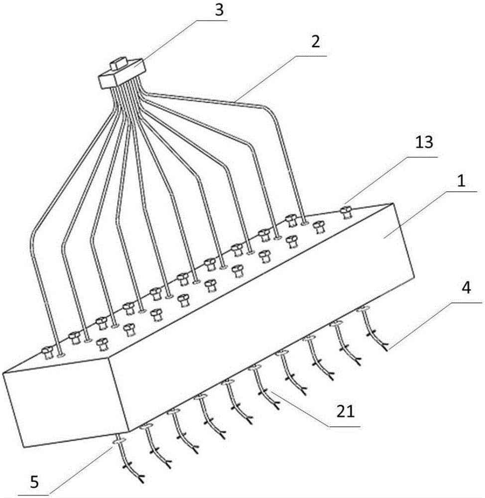
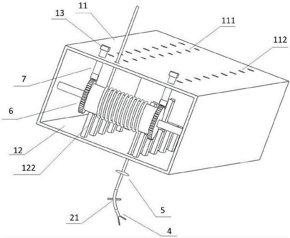
[0040] The electrocardiogram lead wire transceiver apparatus of the present embodiment comprises transceiver box 1, lead wire 2, automatic rebound device, rebound preventing device; Connection, the lead wire 2 is wound on the automatic rebound device; the top surface 11 of the transceiver box 1 is provided with a first outlet hole 111, and one end of the lead wire is connected to the plug 3 through the first outlet hole 11; the bottom surface of the transceiver box 12 A second outlet hole 121 is provided, and the other end of the lead wire 2 passes through the second outlet hole 121 to be connected to the test terminal 4 .

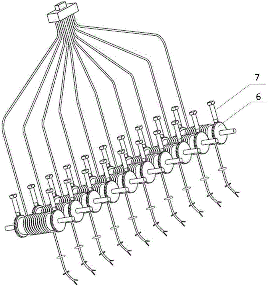
[0041] The rebound prevention device includes a circular baffle 6 and a brake bar 7 . The automatic rebound device includes a rubber band 8 and a rotating shaft 9; One side of the circular baffle 6 is fixedly connected with the rotating shaft 9 , the other side of the circular...

Embodiment 2

[0049] Embodiment 2 Electrocardiogram lead wire sending and receiving device

[0050] The electrocardiogram lead wire transceiver apparatus of the present embodiment comprises transceiver box 1, lead wire 2, automatic rebound device, rebound preventing device; Connection, the lead wire 2 is wound on the automatic rebound device; the top surface 11 of the transceiver box 1 is provided with a first outlet hole 111, and one end of the lead wire is connected to the plug 3 through the first outlet hole 11; the bottom surface of the transceiver box 12 A second outlet hole 121 is provided, and the other end of the lead wire 2 passes through the second outlet hole 121 to be connected to the test terminal 4 .

[0051] The rebound prevention device includes a circular baffle 6 and a brake bar 7 . The automatic rebound device includes a rubber band 8 and a rotating shaft 9; One side of the circular baffle 6 is connected with the rotating shaft 9 , the other side of the circular baffle ...

Embodiment 3

[0060] Embodiment 3 electrocardiogram lead wire sending and receiving device

[0061] The electrocardiogram lead wire transceiver apparatus of the present embodiment comprises transceiver box 1, lead wire 2, automatic rebound device, rebound preventing device; Connection, the lead wire 2 is wound on the automatic rebound device; the top surface 11 of the transceiver box 1 is provided with a first outlet hole 111, and one end of the lead wire is connected to the plug 3 through the first outlet hole 11; the bottom surface of the transceiver box 12 A second outlet hole 121 is provided, and the other end of the lead wire 2 passes through the second outlet hole 121 to be connected to the test terminal 4 .

[0062] The rebound prevention device includes a circular baffle 6 and a brake bar 7 . The automatic rebound device comprises a hollow shaft 14, a shaft core 15 positioned at the center of the hollow shaft 14, a clockwork spring 16 connecting the hollow shaft 14 and the shaft co...


PUM


Abstract

The invention discloses an electrocardiogram lead wire retraction and release appliance. The appliance comprises a retraction and release box, a lead wire, an automatic rebound device and a rebound stopping device; the automatic rebound device and the rebound stopping device are arranged in the retraction and release box and connected with the retraction and release box, and the lead wire is wound on the automatic rebound device; a first wire outlet 111 is formed in the top surface 11 of the retraction and release box 1, and one end of the lead wire penetrates through the first wire outlet 11 and is connected with a plug 3; a second wire outlet 121 is formed in the bottom surface 12 of the retraction and release box, and the other end of the lead wire 2 penetrates through the second wire outlet 121 and is connected with a test terminal 4. The electrocardiogram lead wire retraction and release appliance can realize automatic retraction and release of the lead wire, avoid mutual winding of lead wires, save the time and simultaneously prolong the service life of the lead wire.

Description

technical field [0001] The invention belongs to the field of medical devices, and relates to a device for sending and receiving electrocardiogram lead wires. Background technique [0002] The electrocardiogram machine is a commonly used instrument for recording electrocardiograms in the medical department. The lead wires of the currently used electrocardiogram machines are mainly divided into three groups: one group has 6 chest lead wires, and the other two groups are upper limb lead wires and lower limb lead wires. There are two connection wires each, and one end of the 10 lead wires is connected with the electrocardiograph, and the other end is connected with the suction cup and the electrode clip. The lead wires of the ECG machine are relatively long, generally about 1.5 meters, and relatively concentrated so many slender lead wires are easy to cause the lead wires to become entangled during use, making it difficult to sort out the clues. At the same time, the lead wires ...

Claims


Application Information

Patent Timeline
Patent Type & Authority Applications(China)
IPC IPC(8): B65H75/44B65H75/48A61B5/0402A61B90/00
CPCA61B5/318B65H75/4431B65H75/48B65H2701/34
Inventor 沈春健刘炜高顺刘超谢不敏南洋曲胜付佳玉吴文哲葛尧
Owner 沈阳医学院附属第二医院
Learn More