Power transmission wire tensioning and straightening device

A transmission line and straightening technology, applied in the direction of overhead line/cable equipment, etc., can solve the problems of low work efficiency, transmission line springback, inconvenient operation, etc., and achieve the effect of simple structure, preventing loose strands, and smooth movement

Inactive Publication Date: 2016-11-23
SHANGHE COUNTY POWER SUPPLY CO STATE GRID SHANDONG ELECTRIC POWER CO +1
View PDF8 Cites 12 Cited by
  • Summary
  • Abstract
  • Description
  • Claims
  • Application Information

AI Technical Summary

Problems solved by technology

During the deployment of power transmission and distribution lines, due to the long tensile section of the line, the transmission line often has dead bends or slow bends. In order to ensure the erection of the transmission line, it is necessary to remove the dead bends or slow bends in time. In the existing dead bend or slow bend treatment, the staff mainly use wrench and pliers to correct and straighten the work, or straighten with the help of pulling force, and use wrench or pliers to straighten, which has low work efficiency, inconvenient operation and easy loosening of power lines. The phenomenon of strands, the use of pulling force to straighten the work is labor-intensive, the pulling equipment is inconvenient to move, and the power line is prone to rebound problems

Method used


Image

  • Power transmission wire tensioning and straightening device
  • Power transmission wire tensioning and straightening device
  • Power transmission wire tensioning and straightening device

Examples


Embodiment Construction

[0022] Below will combine specific embodiment and appended Figure 1-5 , clearly and completely describe the technical solutions in the embodiments of the present invention, obviously, the described embodiments are only some preferred embodiments of the present invention, not all the embodiments. Those skilled in the art can make similar modifications without departing from the connotation of the present invention, so the present invention is not limited by the specific embodiments disclosed below.

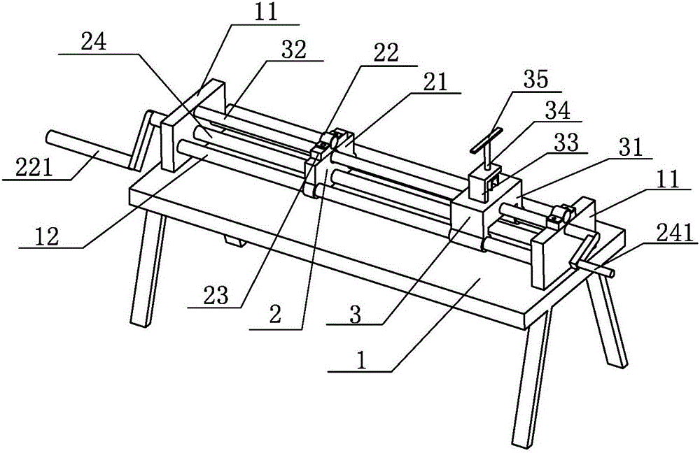
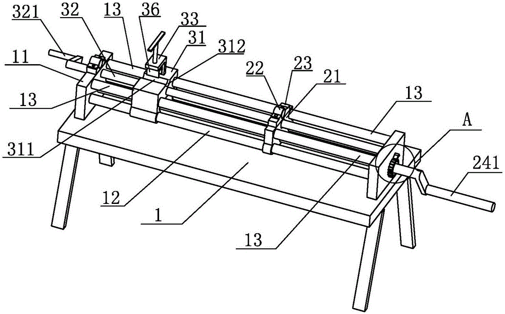
[0023] A power transmission line tension straightening device (such as figure 1 shown), including a bracket 1, a tensioning mechanism 2 and a straightening mechanism 3, the bracket 1 includes a support platform, two opposite support vertical plates 11 are arranged at the two ends of the support platform, and the support Two first guide rods 12 parallel to each other are arranged between the vertical plates 11 . In this specific embodiment, the two first guide rods 12 are parallel...


PUM


Abstract

The invention provides a power transmission wire tensioning and straightening device, which comprises a support frame, a tensioning mechanism and a straightening mechanism, wherein the support frame comprises a support platform; two opposite support vertical plates are arranged at the two ends of the support platform; two mutually parallel first guide rods are arranged between the support vertical plates; the tensioning mechanism comprises a tensioning slide block and a pulling lead screw; the tensioning lead screw is arranged between the two support vertical plates in a sleeving way; the tensioning slide block is arranged on the two first guide rods in a sleeving way; the straightening mechanism comprises a straightening slide block and a compression wheel. The power transmission wire tensioning and straightening device has the advantages that the structure is simple; the operation is convenient; the carrying is easy; during the power transmission line erection, the tensioning mechanism and the straightening mechanism in the power transmission wire tensioning and straightening device can be flexibly used for performing correction treatment on the bent position on a power transmission line, and the goal of fast and efficiently sorting the bent position on the power transmission line can be achieved.

Description

technical field [0001] The invention relates to a power transmission line tensioning and straightening device used in the field of power supply. Background technique [0002] With the continuous development of my country's economy, there are more and more power supply projects, resulting in an increasing workload for the erection of power transmission and distribution lines. During the deployment of power transmission and distribution lines, due to the long tensile section of the line, the transmission line often has dead bends or slow bends. In order to ensure the erection of the transmission line, it is necessary to remove the dead bends or slow bends in time. In the existing dead bend or slow bend treatment, the staff mainly use wrench and pliers to correct and straighten the work, or straighten with the help of pulling force, and use wrench or pliers to straighten, which has low work efficiency, inconvenient operation and easy loosening of power lines. The phenomenon of...

Claims


Application Information

Patent Timeline
Patent Type & Authority Applications(China)
IPC IPC(8): H02G1/04
CPCH02G1/04
Inventor 姜祥梅杨敬敬李霞邢春霞许怡君牛飞飞
Owner SHANGHE COUNTY POWER SUPPLY CO STATE GRID SHANDONG ELECTRIC POWER CO
Why Eureka
Try Eureka