Novel pipe pushing and pulling device

A new type of sliding installation technology, which is applied in pipeline laying and maintenance, pipes/pipe joints/fittings, mechanical equipment, etc., can solve problems such as poor flexibility, difficult installation, and high requirements for pipe alignment accuracy, so as to improve flexibility and prevent The effect of pipe springback

Pending Publication Date: 2020-02-14
ORIENT ENERGY & TECH CO LTD
View PDF0 Cites 12 Cited by
  • Summary
  • Abstract
  • Description
  • Claims
  • Application Information

AI Technical Summary

Problems solved by technology

[0002] The pipe pusher is used in the construction of large-diameter, long-distance high-pressure pipelines. It is the core device of the direct pipe-laying process. However, the pipe pusher is large in size, has poor flexibility after entering the site, and is difficult to install. Appropriate adjustments, and the high precision requirements for the alignment of the pipeline in the originating shaft during construction, so the flexibility of the pipe pusher needs to be resolved urgently

Method used


Image

  • Novel pipe pushing and pulling device
  • Novel pipe pushing and pulling device

Examples


Embodiment Construction

[0018] In order to enable those skilled in the art to better understand the technical solution of the application, the application will be described in detail below in conjunction with the accompanying drawings. The description in this part is only exemplary and explanatory, and should not have any limiting effect on the protection scope of the application. .

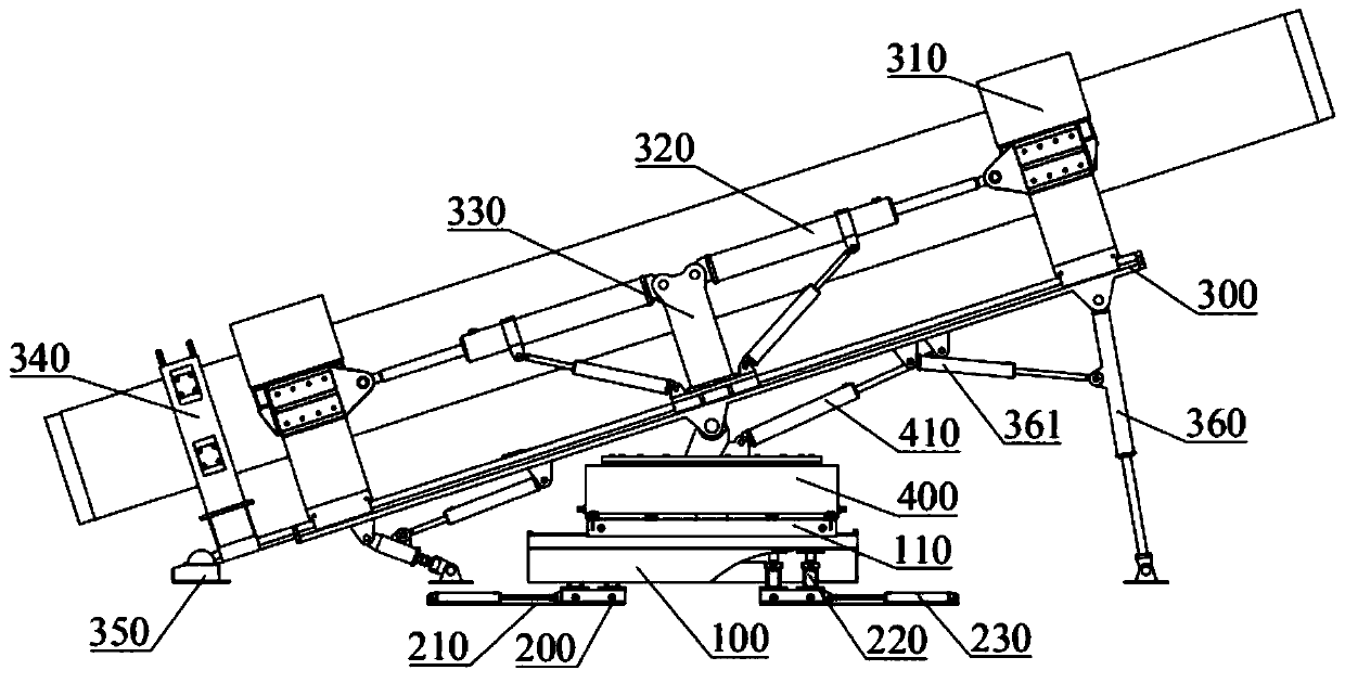
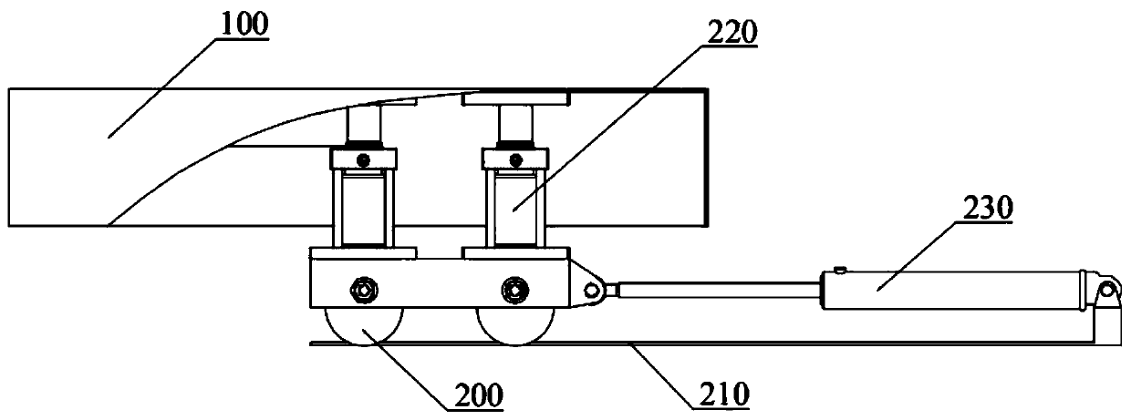
[0019] Please refer to figure 1 and figure 2 , the present embodiment provides a novel push-pull tube device, including a base 100, a push-pull tube mechanism and a walking mechanism are provided on the base 100; the push-pull tube mechanism is rotatably mounted on the base 100; Mobile plate 210 below; Walking wheel 200 is connected with base 100 by lifting hydraulic cylinder 220, is provided with walking hydraulic cylinder 230 along the moving direction of walking wheel 200 on moving plate 210, and the two ends of walking hydraulic cylinder 230 are respectively connected with walking wheel 200 and The moving plate 2...


PUM


Abstract

The invention provides a novel pipe pushing and pulling device. The device comprises a base, a pipe pushing and pulling mechanism and a walking mechanism are arranged on the base, the pipe pushing andpulling mechanism is rotatably mounted on the base, the walking mechanism comprises walking wheels and moving plates on the lower portions of the walking wheels, the walking wheels are connected withthe base through lifting hydraulic cylinders, and can completely shrink into the base, walking hydraulic cylinders arranged in the moving direction of the walking wheels are arranged on the moving plates, and two ends of the walking hydraulic cylinders are connected with the moving plates and the walking wheels. According to the technical scheme, through the lifting hydraulic cylinders, supporting stress of the walking wheels and the base can be switched, in cooperation with the walking hydraulic cylinders, stepping walking is achieved, the pipe pushing and pulling pipe mechanism is rotatablymounted on the base, a pushing and pulling mechanism is controlled to do 360-degree rotation in the horizontal direction, and multi-station pipe feeding of the pushing and pulling mechanism can be achieved.

Description

technical field [0001] The application relates to the technical field of pipeline laying, in particular to a novel push-pull pipe device. Background technique [0002] The pipe pusher is used in the construction of large-diameter, long-distance high-pressure pipelines. It is the core device of the direct pipe-laying process. However, the pipe pusher is large in size, has poor flexibility after entering the site, and is difficult to install. Proper adjustment is required, and the alignment accuracy of the pipeline in the originating shaft is relatively high during construction, so the flexibility of the pipe pusher needs to be resolved urgently. Contents of the invention [0003] In view of the above-mentioned defects or deficiencies in the prior art, it is desired to provide a novel push-pull tube device. [0004] The application provides a novel push-pull tube device, including a base; the base is provided with a push-pull tube mechanism and a walking mechanism; the push...

Claims


Application Information

Patent Timeline
Patent Type & Authority Applications(China)
IPC IPC(8): F16L1/028F16L1/06
CPCF16L1/028F16L1/06
Inventor 肖鑫源魏秦文尹永清尹永奇祖宝华张士明王圣林王瑞刘洋韩涛
Owner ORIENT ENERGY & TECH CO LTD
Why Eureka
Try Eureka