Screw type buffer hinge

A spiral and hinge technology, applied in the hardware field, can solve the problems of reducing the service life of the door, passing the door and the door frame, and losing the cushioning effect, so as to avoid the collision between the door and the door frame, facilitate spring installation, and achieve the effect of buffering effect

Active Publication Date: 2017-05-31
温州瓯海利尔达五金制品有限公司
View PDF5 Cites 13 Cited by
  • Summary
  • Abstract
  • Description
  • Claims
  • Application Information

AI Technical Summary

Problems solved by technology

[0002] At present, ordinary hinges are widely used as hinges for building doors and windows, and all of them are traditional folding hinges, which only have a hinge function. During the closing process, if the door itself cannot be closed due to the inertia of the door itself, the user Usually, it is necessary to forcefully push one side of the door to move toward the door frame. This way of closing the door may easily lead to excessive force, resulting in excessive collision sound between the door and the door frame or a huge impact between the door and the door frame, which will reduce the service life of the door. In order to avoid detailed collisions , People will use hydraulic buffer hinges, but hydraulic buffer hinges are expensive and bulky, and hydraulic oil leakage is prone to occur during use, thus losing the buffering effect and reducing the service life

Method used


Image

  • Screw type buffer hinge
  • Screw type buffer hinge
  • Screw type buffer hinge

Examples


Embodiment Construction

[0031] Refer to attached Figure 1 to Figure 7 A spiral buffer hinge of the present invention is further described in detail.

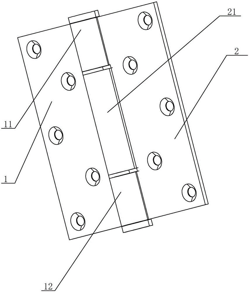
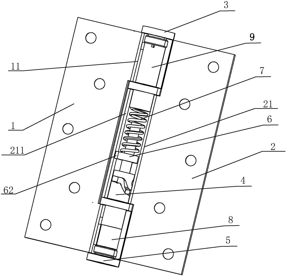
[0032] From figure 1 It can be seen that a spiral buffer hinge includes a left hinge piece 1 and a right hinge piece 2 that can rotate relatively coaxially, and the upper and lower parts of one side of the left hinge piece 1 are provided with an upper sleeve 11 and a lower sleeve. Pipe 12, one side of the right hinge 2 is provided with a middle sleeve 21, when the left hinge 1 and the right hinge 2 are assembled, the middle sleeve 21 is placed on the upper sleeve 11 and the lower sleeve 12 between the middle casing 21 and the upper casing 11 is provided with an upper gasket, between the middle casing 21 and the lower casing 12 is provided with a lower gasket, and the upper gasket and the lower gasket An oil storage cavity is formed with the middle casing, and lubricating oil is filled in the oil storage cavity.

[0033] From figure 1 and Figure ...


PUM


Abstract

The invention discloses a screw type buffer hinge. Upper and lower portions of one side of a left hinge piece are provided with an upper sleeve and a lower sleeve. One side of a right hinge piece is provided with a middle sleeve. An upper end cover is disposed in the upper sleeve. A fixing sleeve, a damper and a lower end cover are disposed in the lower sleeve. A side wall of one end portion of the fixing sleeve is provided with a rotating chute. A screw member is disposed in the middle sleeve. One end portion of the screw member is fixedly sleeved with a spring. One end of the spring extends towards the inside of the upper sleeve and is fixed in the upper sleeve. The other end portion of the screw member is provided with a rotating pin cooperated with the rotating chute. When the rotating pin moves in the rotating chute, the screw member is driven to move in the middle sleeve up and down, and the screw member drives the right hinge piece to rotate relative to the left hinge piece, so that a door is closed. The door can be closed without being powerfully pushed by a user, collision between the door and a doorframe can be effectively prevented, and compared with a hydraulic hinge, the screw type buffer hinge has the advantages that the screw type buffer hinge is simple in structure and long in service lifetime, and oil leakage can be prevented.

Description

technical field [0001] The invention relates to the field of hardware, more specifically, it relates to a spiral buffer hinge. Background technique [0002] At present, ordinary hinges are widely used as hinges for building doors and windows, and all of them are traditional folding hinges, which only have a hinge function. During the closing process, if the door itself cannot be closed due to the inertia of the door itself, the user Usually, it is necessary to forcefully push one side of the door to move towards the door frame. This way of closing the door may easily lead to excessive force, resulting in excessive collision sound between the door and the door frame or a huge impact between the door and the door frame, which will reduce the service life of the door. In order to avoid detailed collisions , People will use hydraulic buffer hinges, but hydraulic buffer hinges are expensive and bulky, and hydraulic oil leakage is prone to occur during use, thus losing the bufferi...

Claims


Application Information

Patent Timeline
Patent Type & Authority Applications(China)
IPC IPC(8): E05D3/02E05D5/14E05D11/10E05F1/14E05F5/02
CPCE05D3/02E05D5/14E05D11/1028E05D2011/1092E05F1/14E05F5/027
Inventor 陈光次
Owner 温州瓯海利尔达五金制品有限公司
Why Eureka
Try Eureka