Damper for lifting rod of automobile trunk

A trunk and lifting rod technology, which is applied in the field of dampers, can solve the problems that the lifting device cannot support the trunk door, the opening and closing force of the door is unreasonable, and the trunk is inconvenient to use, so as to achieve a compact internal structure design and open It is convenient and fast to close and close, and the overall structure design is reasonable.

Pending Publication Date: 2017-05-31
DONGGUAN CITY YESSUN ELECTRONICS
0 Cites 1 Cited by

AI-Extracted Technical Summary

Problems solved by technology

[0003] Because the trunk door is very heavy, the lifting device in the extended state cannot support the weight of the trunk door. When closing the door, due to the weight of the trunk door, the force in the closing process is very large, which appears under the actio...

Abstract

The invention discloses a damper for a lifting rod of an automobile trunk. The damper comprises a shell; the shell is internally provided with an input shaft, an inner core, an outer core and an output shaft; the upper end of the inner core is inserted into the outer core; the lower end of the output shaft is sequentially inserted into the outer core and the inner core; the upper end of the input shaft is sequentially inserted into the inner core and the output shaft; the upper end of the input shaft is connected with the lower end of the output shaft through a screw; the outer wall of the inner core is sleeve with an inner core spring, and the inner core spring makes contact with the inner wall of the outer core; the outer wall of the outer core is sleeved with an outer core spring, and the outer core spring makes contact with the inner wall of the shell; the inner core spring is squeezed to be expanded through the output shaft, the jacking force of the inner core spring to the inner wall of the outer core is increased, then, the outer core and the inner core are driven to rotate in sequence, and the effect that reduced power is transmitted into the input shaft is achieved. The damper is reasonable in overall structural design, high in stability and capable of providing appropriate resistance for the stretching out and drawing back processes of the lifting rod, so that a door of the trunk is opened or closed with appropriate strength, and opening and closing are more convenient and quicker.

Application Domain

Technology Topic

Image

  • Damper for lifting rod of automobile trunk
  • Damper for lifting rod of automobile trunk
  • Damper for lifting rod of automobile trunk

Examples

  • Experimental program(1)

Example Embodiment

[0022] In order to further explain the technical means and effects of the present invention to achieve the predetermined purpose, the specific implementation of the present invention will be described in detail below with reference to the accompanying drawings and preferred embodiments.
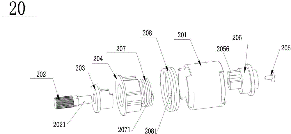
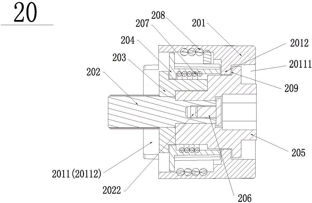
[0023] Please refer to Figure 1 to Figure 5 , The embodiment of the present invention provides a damper 20 for an automobile trunk lifting rod, including a housing 201 in which an input shaft 202, an inner core 203, an outer core 204, and an output shaft 205 are respectively arranged, wherein The upper end of the inner core 203 is inserted into the outer core 204, the lower end of the output shaft 205 is inserted into the outer core 204 and the inner core 203 in turn, the upper end of the input shaft 202 is inserted into the inner core 203 and the output shaft 205 in turn, the upper end of the input shaft 202 and The lower ends of the output shaft 205 are connected by a screw 206, and an inner core spring 207 is sleeved on the outer wall of the inner core 203, and the inner core spring 207 is in contact with the inner wall of the outer core 204, and is sleeved on the outer wall of the outer core 204 There is an outer core spring 208, and the outer core spring 208 is in contact with the inner wall of the housing 201; the inner core spring 207 is squeezed by the output shaft 205 to expand the inner core spring 207 and increase the resistance of the inner core spring 207 to the inner wall of the outer core 204 The force drives the outer core 204 and the inner core 203 to rotate in turn, so that the reduced power is transmitted to the input shaft 202.
[0024] Such as Figure 4 As shown, the inner core 203 includes an inner core boss 2031 and an inner core shaft 2032 arranged on the inner core boss 2031. An inner core insertion hole 2033 is provided in the direction of the central axis of the inner core 203, and the inner core is inserted The hole 2033 sequentially penetrates the inner core boss 2031 and the inner core shaft 2032, and a side opening 2034 is opened on the side of the inner core shaft 2032, and a hook 20341 is formed on both sides of the side opening 2034. The upper end of the hook 20341 has a gap 20342; the inner core spring 207 has two inner spring hooks 2071, the inner core spring 207 is sleeved outside the inner core shaft 2032, and the two inner spring hooks 2071 are respectively clamped in On the hook side 20341.
[0025] Such as image 3 As shown, the outer core 204 includes an outer core boss 2041 and an outer core shaft 2042 disposed on the outer core boss 2041. An outer core insertion hole 2043 is provided in the direction of the central axis of the outer core 204, and the outer core inserts The hole 2043 sequentially penetrates the outer core boss 2041 and the outer core shaft 2042, and the outer wall of the outer core 204 is provided with a number of strip grooves 2044, and the upper ends of the arms on both sides of the strip groove 2044 respectively have an arc surface 20441; The outer core spring 208 has two outer spring hooks 2081, the outer core spring 208 is sleeved outside the outer core shaft 2042, and the two outer spring hooks 2081 are respectively clamped on the strip groove 2044.
[0026] Such as Figure 5 As shown, the output shaft 205 includes an output upper shaft 2051, an output shaft boss 2052, an output middle shaft 2053, and an output lower shaft 2054, which are sequentially arranged from top to bottom, wherein an output shaft 205 is provided in the direction of the central axis of the output shaft 205. Shaft socket 2055, the output shaft socket 2055 sequentially penetrates the output upper shaft 2051, the output shaft boss 2052, the output middle shaft 2053 and the output lower shaft 2054. The output lower shaft 2054 is provided with an extrusion block 2056 on the side of the The pressing block 2056 and the output lower shaft 2054 are integrally formed. In this embodiment, the outer diameter of the output shaft boss 2052 is larger than the outer diameter of the output middle shaft 2053, the outer diameter of the output middle shaft 2053 is larger than the outer diameter of the output upper shaft 2051, and the outer diameter of the output upper shaft 2051 It is larger than the outer diameter of the output lower shaft 2054.
[0027] Such as figure 1 As shown, the input shaft 202 has an input shaft 2021, and the front end of the input shaft 2021 has an input shaft jack 2022.
[0028] Such as figure 2 As shown, a housing insertion hole 2011 is provided in the direction of the central axis of the housing 201, and an annular convex ring 2012 is provided on the inner wall of the housing insertion hole 2011. The annular convex ring 2012 divides the housing insertion hole 2011 into an upper hole 20111 and lower jack 20112.
[0029] Such as figure 2 As shown, the inner core shaft 2032 of the inner core 203 is inserted into the outer core insertion hole 2043 from the lower end of the outer core 204, and the output middle shaft 2053 and the output lower shaft 2054 of the output shaft 205 are inserted into the outer core insertion hole from the upper end of the outer core 204 In 2043, the lower output shaft 2054 is inserted into the inner core insertion hole 2033, and the extrusion block 2056 on the side of the lower output shaft 2054 is located in the side opening 2034 on the side of the inner mandrel 2032, so that the upper end of the outer mandrel 2042 is connected to the output A slot 209 is formed between the shaft bosses 2052, and the annular convex ring 2012 in the housing 201 is clamped in the slot 209 so that the upper output shaft 2051 of the output shaft 205 and the output shaft boss 2052 are located in the housing insert. In the upper jack 20111 of the hole 2011, the input shaft 202, the inner core 203, the outer core 204, and the output shaft 2053 and the output lower shaft 2054 of the output shaft 205 are respectively located in the lower jack 20112 of the housing jack 2011 The upper end of the input shaft 202 is sequentially inserted into the inner core boss 2031 and the output shaft socket 2055, so that the input shaft 2021 of the input shaft 202 is inserted into the output shaft socket 2055, and the screw 206 is inserted into the input shaft socket 2022 , The input shaft 202 is limited to the output shaft jack 2055.
[0030] The damper 20 provided in this embodiment is particularly suitable for use in the lifting rod of the trunk of an automobile.
[0031] When the trunk is opened upwards, the resistance generated by the damper is very small, so that the power provided by the drive mechanism is transmitted 1:1.
[0032] When the trunk is closed downwards, due to the gravity of the trunk door, power is transmitted to the output shaft 205 of the damper 20, and the pressing block 2056 on the output shaft 205 presses the inner spring hook of the inner core spring 207 downward 2071, if the inner core spring 207 is expanded, the friction force between the inner core spring 207 and the inner wall of the outer core 204 becomes greater, that is, the inner core spring 207 has a significantly greater resistance to the inner wall of the outer core 204; and at this time, it drives the outer The core 204 rotates, and the outer core spring 208 is in a contracted state on the outside of the outer core 204, and the friction between it and the inner wall of the housing 201 is reduced. At this time, due to the rotation of the outer core 204, it will drive the rotation of the inner core 203, and finally transmit power. To the input shaft 202.
[0033] The damper for the lifting rod of the trunk of the automobile provided by the present invention has compact internal structure design, reasonable overall structure design and high stability, provides suitable resistance for the expansion and contraction process of the lift rod, and enables the opening and closing of the trunk door Appropriate strength makes opening and closing more convenient and quick.
[0034] The above are only preferred embodiments of the present invention, and do not limit the technical scope of the present invention. Therefore, the use of the same or similar technical features as the above-mentioned embodiments of the present invention falls within the protection scope of the present invention.

PUM

no PUM

Description & Claims & Application Information

We can also present the details of the Description, Claims and Application information to help users get a comprehensive understanding of the technical details of the patent, such as background art, summary of invention, brief description of drawings, description of embodiments, and other original content. On the other hand, users can also determine the specific scope of protection of the technology through the list of claims; as well as understand the changes in the life cycle of the technology with the presentation of the patent timeline. Login to view more.

Similar technology patents

Embedded-speed-reducer type direct-current servo Mecanum wheel

PendingCN111775619ACompact internal designReduce volumeElectric propulsion mountingMotor depositionMecanum wheelServo
Owner:扬州西格玛自动化设备有限公司

Elevator composite counterweight grinding ultraflat production line

InactiveCN106181651AThe overall structure design is reasonableInnovative wayGrinding carriagesGrinding feedersDiamond grindingPower belt
Owner:TIANJIN ELEVATOR ELEVATOR PARTS

Classification and recommendation of technical efficacy words

Why Eureka
Try Eureka