Unlock instant, AI-driven research and patent intelligence for your innovation.
All-position automatic welding traveling device and track
What is Al technical title?
Al technical title is built by PatSnap Al team. It summarizes the technical point description of the patent document.
An automatic welding and walking device technology, applied in welding accessories, electrode support devices, devices for supporting electrode clips, etc., can solve the problems of complex structure, high maintenance cost, large volume, etc., and achieve compact internal design, convenient installation, and volume. small effect
Inactive Publication Date: 2021-02-12
成都百竣科技有限公司
View PDF6 Cites 0 Cited by
Summary
Abstract
Description
Claims
Application Information
AI Technical Summary
This helps you quickly interpret patents by identifying the three key elements:
Problems solved by technology
Method used
Benefits of technology
Problems solved by technology
[0005] 1. During the welding process, the posture of the trolley and the welding gun need to be adjusted frequently, and there are many joints, so the adjustment is inconvenient
[0006] 2. Large volume and complicated structure, which affect installation efficiency and high maintenance cost
Method used
Image
Click on the blue label to locate the original text in one second.
Reading with bidirectional positioning of images and text.
Examples
Embodiment 1
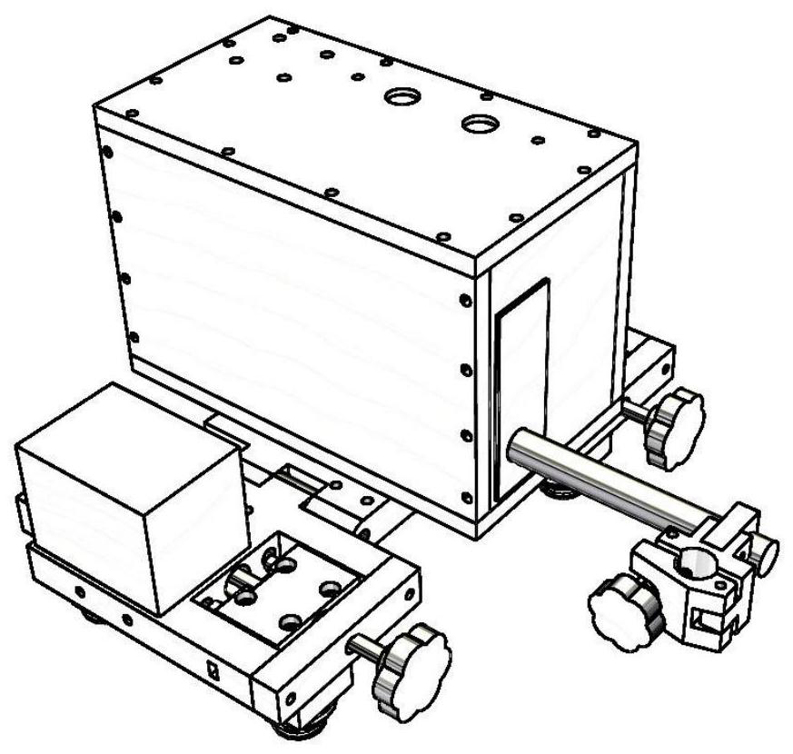
[0043] An all-position automatic welding walking device, used for walking on a track with teeth on one side, including: a front frame assembly, a rear frame assembly, and a rear frame assembly connected between the front frame assembly and the rear frame assembly the middle frame;
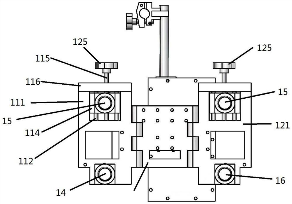
[0044]The front frame assembly includes a front frame 121, a first driven wheel 15 on one side below the front frame 121, a second driven wheel 16 on the other side below the front frame 121, and a wheel for adjusting the first driven wheel. 15 and the driven wheel displacement adjusting device of the distance between the second driven wheel 16;
[0045] Described rear vehicle frame assembly comprises rear vehicle frame 111, the driving wheel 14 of one side below rear vehicle frame 111, the first driven wheel 15 of the other side below rear vehicle frame 111, and is used for adjusting the first driven wheel 15 and The driven wheel displacement adjustment device for the distance between the driving...
Embodiment 2
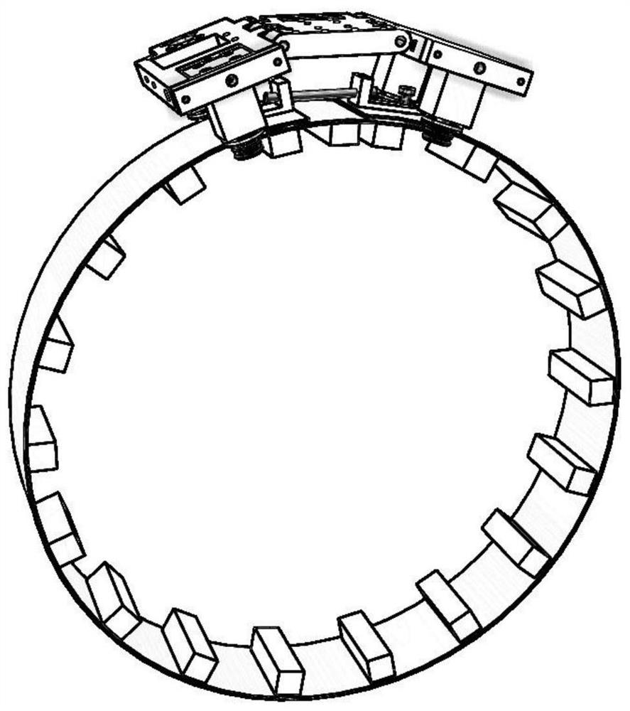
[0060] Such as Figure 10 As shown, this embodiment also provides a track of the all-position automatic welding traveling device, which is used to make the full-position automatic welding traveling device walk on it. The position of the track corresponds to the position of the guide groove of the second layer. The teeth of the upper layer of the track are meshed with the gears in the guide groove of the second layer. The gears in the slots mesh.
PUM
Abstract
The invention provides an all-position automatic welding walking device and a track for walking on a track with teeth on one side, a front frame assembly, a rear frame assembly, and a middle frame; the front frame assembly includes a front Vehicle frame, first driven wheel, second driven wheel, driven wheel displacement adjustment device, rear frame assembly includes rear frame, driving wheel, first driven wheel, driven wheel displacement adjustment device, motor, worm, turbine, from The driving wheel displacement adjustment device includes a slider, a main shaft, a slide bar, a rod, a spring, a stopper, and a knob. The driving wheel and the second driven wheel are located on the side with teeth on the track. The front frame assembly and the rear frame assembly The finished first driven wheels are all located on the side without teeth on the track; the internal design of the present invention is compact, the volume is smaller, and the weight is lighter at the same time, and the angle between the front and rear two groups of wheels can be changed from -10 degrees to 180 degrees , the walking device can meet the welding applications of planes, large-diameter pipes, small-diameter pipes and components with large curvature.
Description
technical field [0001] The invention belongs to the technical field of automatic welding, in particular to an all-position automatic welding traveling device and a track matched with the traveling device. Background technique [0002] Metal sheets are widely used in industry, infrastructure and other fields. A large number of connections between components use arc welding. At present, most industries use welders for manual welding in construction. Welders are labor-intensive and work in harsh environments. Welding quality is limited by welders The operating level and production efficiency are also low. [0003] In order to solve the above problems, automatic welding has begun to be applied in many industries. [0004] Although the existing trolley walking device can meet some welding requirements, there are still some shortcomings: [0005] 1. During the welding process, the postures of the trolley and the welding torch need to be adjusted frequently, and there are many jo...
Claims
Application Information
Patent Timeline
Application Date:The date an application was filed.
Publication Date:The date a patent or application was officially published.
First Publication Date:The earliest publication date of a patent with the same application number.
Issue Date:Publication date of the patent grant document.
PCT Entry Date:The Entry date of PCT National Phase.
Estimated Expiry Date:The statutory expiry date of a patent right according to the Patent Law, and it is the longest term of protection that the patent right can achieve without the termination of the patent right due to other reasons(Term extension factor has been taken into account ).
Invalid Date:Actual expiry date is based on effective date or publication date of legal transaction data of invalid patent.

